For the circuit shown in Fog. Q2, determine the following: (a) The total impedance seen by the source (b) The total voltage across the capacitor (c) The active, reactive, apparent power and the power factor of the voltage source 35 jul mor 30<20° }2_2 jin зл www -j6n jza
For the circuit shown in Fog. Q2, determine the following: (a) The total impedance seen by the source (b) The total voltage across the capacitor (c) The active, reactive, apparent power and the power factor of the voltage source 35 jul mor 30<20° }2_2 jin зл www -j6n jza

Power System Analysis and Design (MindTap Course List)
6th Edition
ISBN:9781305632134
Author:J. Duncan Glover, Thomas Overbye, Mulukutla S. Sarma
Publisher:J. Duncan Glover, Thomas Overbye, Mulukutla S. Sarma
Chapter2: Fundamentals
Section: Chapter Questions
Problem 2.17MCQ: Consider the load convention that is used for the RLC elements shown in Figure 2.2 of the text. A....

Related questions

Question
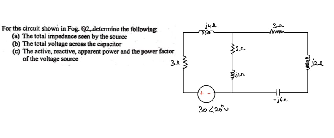
Transcribed Image Text:For the circuit shown in Fog. Q2, determine the following:
(a) The total impedance seen by the source
(b) The total voltage across the capacitor
(c) The active, reactive, apparent power and the power factor
of the voltage source
Зл
jul
mon
+
30<20°
≤2_22
jin
3-
-j6n
colelel
j2-2
Expert Solution
This question has been solved!
Explore an expertly crafted, step-by-step solution for a thorough understanding of key concepts.

Step by step
Solved in 5 steps with 9 images

Knowledge Booster


Learn more about
Need a deep-dive on the concept behind this application? Look no further. Learn more about this topic, electrical-engineering and related others by exploring similar questions and additional content below.Recommended textbooks for you
Power System Analysis and Design (MindTap Course …
Electrical Engineering
ISBN:
9781305632134
Author:
J. Duncan Glover, Thomas Overbye, Mulukutla S. Sarma
Publisher:
Cengage Learning
Power System Analysis and Design (MindTap Course …
Electrical Engineering
ISBN:
9781305632134
Author:
J. Duncan Glover, Thomas Overbye, Mulukutla S. Sarma
Publisher:
Cengage Learning