R 2.2 KQ 3.3 ΚΩ Figure 2.0a: Simple DC Circuit VR=> IR => (mA) IR => (mA) VR E A RVR Figure 2.0b: Simple DC Circuit showing Voltmeter & Ammeter connections 4V 6V 8V 10V Theory MultiSIM Theory MultiSIM Theory MultiSIM Theory MultiSIM Theory result result result result result result result result result Table 2.0: Theoretical and MultiSIM results of the Simple DC Circuit in Figure 2.0 V 15V MultiSIM result
R 2.2 KQ 3.3 ΚΩ Figure 2.0a: Simple DC Circuit VR=> IR => (mA) IR => (mA) VR E A RVR Figure 2.0b: Simple DC Circuit showing Voltmeter & Ammeter connections 4V 6V 8V 10V Theory MultiSIM Theory MultiSIM Theory MultiSIM Theory MultiSIM Theory result result result result result result result result result Table 2.0: Theoretical and MultiSIM results of the Simple DC Circuit in Figure 2.0 V 15V MultiSIM result

Introductory Circuit Analysis (13th Edition)
13th Edition
ISBN:9780133923605
Author:Robert L. Boylestad
Publisher:Robert L. Boylestad
Chapter1: Introduction
Section: Chapter Questions
Problem 1P: Visit your local library (at school or home) and describe the extent to which it provides literature...

Related questions
Question
100%
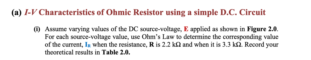
Transcribed Image Text:(a) I-V Characteristics of Ohmic Resistor using a simple D.C. Circuit
(i) Assume varying values of the DC source-voltage, E applied as shown in Figure 2.0.
For each source-
ce-voltage value, use Ohm's Law to determine the corresponding value
of the current, IR when the resistance, R is 2.2 kN and when it is 3.3 kN. Record your
theoretical results in Table 2.0.
Transcribed Image Text:R
E
2.2 ΚΩ
3.3 ΚΩ
+
VR=>
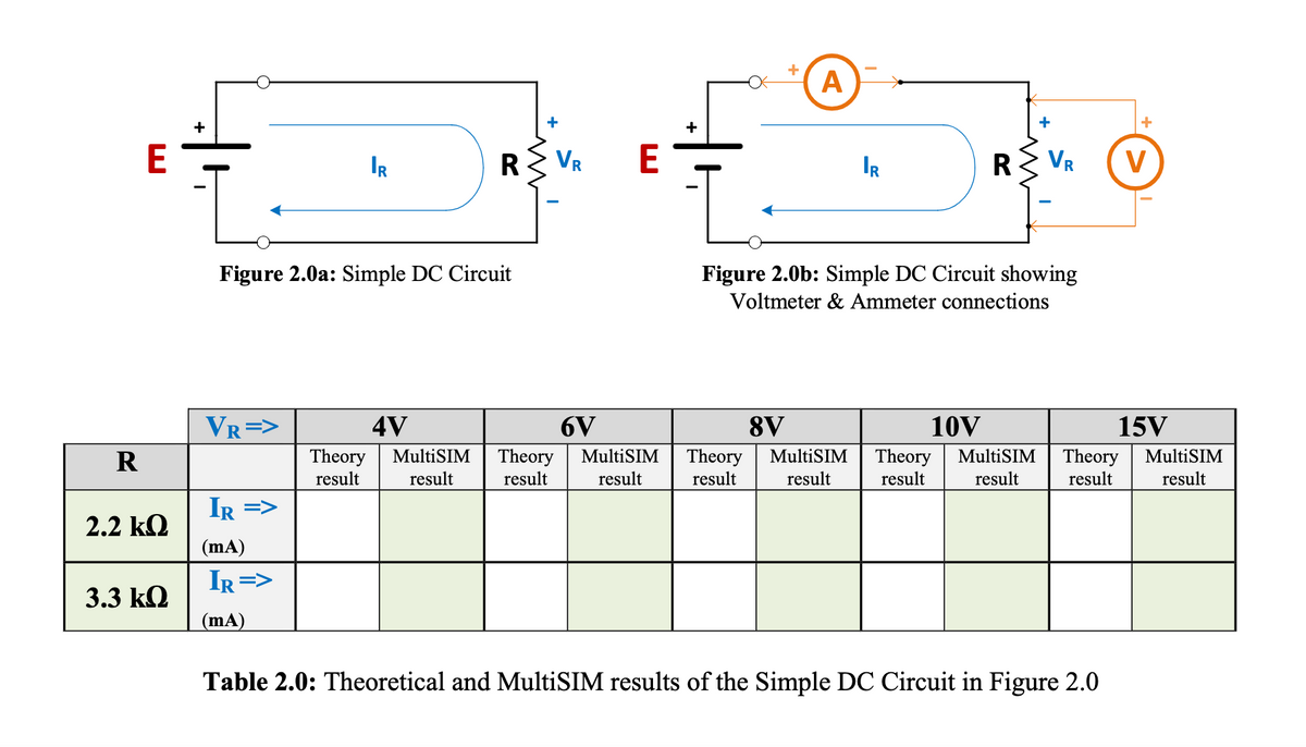
Figure 2.0a: Simple DC Circuit
IR =>
(mA)
IR =>
IR
(mA)
+
RZ VR
E
4V
6V
Theory MultiSIM Theory MultiSIM
result result result result
+
A
IR
R VR
Figure 2.0b: Simple DC Circuit showing
Voltmeter & Ammeter connections
+
Table 2.0: Theoretical and MultiSIM results of the Simple DC Circuit in Figure 2.0
V
8V
10V
15V
Theory MultiSIM Theory MultiSIM Theory MultiSIM
result result result result result result
Expert Solution
This question has been solved!
Explore an expertly crafted, step-by-step solution for a thorough understanding of key concepts.

Step by step
Solved in 5 steps with 5 images

Knowledge Booster


Learn more about
Need a deep-dive on the concept behind this application? Look no further. Learn more about this topic, electrical-engineering and related others by exploring similar questions and additional content below.Recommended textbooks for you
Introductory Circuit Analysis (13th Edition)
Electrical Engineering
ISBN:
9780133923605
Author:
Robert L. Boylestad
Publisher:
PEARSON

Delmar's Standard Textbook Of Electricity
Electrical Engineering
ISBN:
9781337900348
Author:
Stephen L. Herman
Publisher:
Cengage Learning

Programmable Logic Controllers
Electrical Engineering
ISBN:
9780073373843
Author:
Frank D. Petruzella
Publisher:
McGraw-Hill Education
Introductory Circuit Analysis (13th Edition)
Electrical Engineering
ISBN:
9780133923605
Author:
Robert L. Boylestad
Publisher:
PEARSON
Delmar's Standard Textbook Of Electricity
Electrical Engineering
ISBN:
9781337900348
Author:
Stephen L. Herman
Publisher:
Cengage Learning
Programmable Logic Controllers
Electrical Engineering
ISBN:
9780073373843
Author:
Frank D. Petruzella
Publisher:
McGraw-Hill Education

Fundamentals of Electric Circuits
Electrical Engineering
ISBN:
9780078028229
Author:
Charles K Alexander, Matthew Sadiku
Publisher:
McGraw-Hill Education

Electric Circuits. (11th Edition)
Electrical Engineering
ISBN:
9780134746968
Author:
James W. Nilsson, Susan Riedel
Publisher:
PEARSON

Engineering Electromagnetics
Electrical Engineering
ISBN:
9780078028151
Author:
Hayt, William H. (william Hart), Jr, BUCK, John A.
Publisher:
Mcgraw-hill Education,