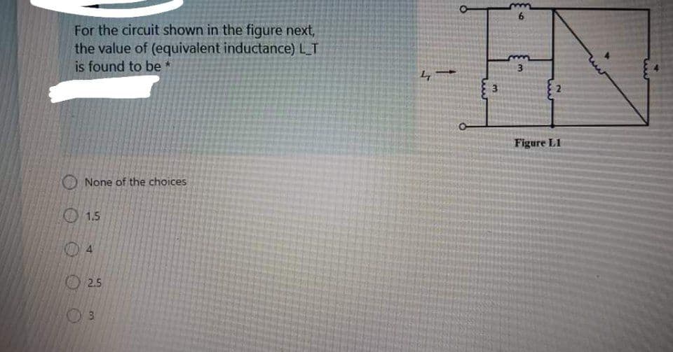
For the circuit shown in the figure next, the value of (equivalent inductance) L_T is found to be * 3. 2. Figure L1
Q: Q1: The steady-state current I flowing in a circuit that contains a resistance R=5, capacitance C…
A:
Q: R Assume first that v, = 12V-u(-t) and X is a capacitor with C = 25mF. + (a) What is the initial…
A: Since you have asked multiple questions in a single request, we will be answering only the first…
Q: QI/ For the network shown in figure (Q1), the switch has been in position "a" for a long time. At…
A: In steady state, the inductor behaves as short circuit and the capacitor behaves as open circuit.…
Q: 2. Reduce the following open loop system into single block and find transient and steady state…
A: a) From the given figure, G1s=s9s+17G2s=9s+32s2+9s+27 Solving given control system,…
Q: In the RL circuit shown below, the switch is open for a long time and closes at t = 0. If Is =…
A:
Q: The capacitor in figure begins to charge after the switch closes at t = 0 [s]. a) What is AVc a very…
A: Once the switch is closed, the capacitor starts charging and the charging of a capacitor takes place…
Q: Q2/ For the network shown in figure (Q2), the switch has been open for a long time before closing at…
A:
Q: CONSIDERING THE CIRCUIT OF FIGURE 2. THE INPUT FUNCTION OF V(T) IS THE VOLTAGE PULSE SHOWN IN FIGURE…
A: First, let us convert the voltage source to current source using source transformation.…
Q: For L1=13, L2=10, L3=18, L4=38, L5=79, L6=39, L7=25 & L8=58 in the circuit shown below, find Leg…
A: In this question we will find L eq between the terminals ab...
Q: Q3/ For the circuit shown, the switch S is closed at t-0, and the voltage readings for capacitor…
A:
Q: CONSIDERING THE CIRCUIT OF FIGURE 2. THE INPUT FUNCTION OF V(T) IS THE VOLTAGE PULSE SHOWN IN FIGURE…
A: Capacitor When a voltage is suddenly applied across a capacitor it will take some time to charge the…
Q: Q1/ For the networks shown in Figures (Q1), the switch has been at position "A" for a long time. At…
A:
Q: b) Given an RL circuit with the equation IP L+ RI = 900, dt where L is the inductance, R is the…
A: We will find the solution using complementary solution and particular integral. Then with given…
Q: The differential equation of a circuit containing a resistance R, capacitance C, and emf di i de e =…
A:
Q: Q.5/ For each system shown in Figure 3, make an accurate plot of the root locus and find the…
A: Since you have posted the questions with multiple subpart so we are supposed to answer 3 subpart.
Q: (b) For the circuit Figure Q1(b), assume the circuit is in a steady state at t = 0¯ before the…
A: The given circuit is shown below. The switch is closed at t=0 sec. And it is mentioned that before…
Q: The switch shown in Figure Q2 has been open for a long time, and the initial charge on the capacitor…
A: The circuit is: for t<0. the circuit is: The voltage across the capacitor initially = 0 Vc0-=0…
Q: For L1=17, L2=14, L3=11, L4=33, L5=70, L6=36, L7=27 & L8=55 in the circuit shown below, find Leg…
A: Resistors, inductors and capacitors form an integral part of any electrical circuit. A source,…
Q: A circuit consists of switches that open or close at t=0, resistances, dc sources, and a single…
A: According to the given problem we will consider a series RL circuit which can be realized as…
Q: For the network shown in figure (Q1), the switch has been in position "a" for a long time. At t-0,…
A: Initial Switch at position a Before time t=0 For long time, inductor act as short circuit. At…
Q: L1 Leg L3 Figure4 lalll ll
A:
Q: a) Write a set of mesh-current equations that describe the circuit given below in terms of the…
A:
Q: For the network shown in figure Q1 below, the switch is closed on to position 1 when t = 0 and then…
A: The circuit shown in the figure is the RC circuit which is DC biased. As the switch move to…
Q: Show that a system of differential equations that describes the currents i, (t) and i,(t) in the…
A:
Q: Linear Differential Equation A simple electrical circuit shown in Figure 5.1 below is designed with…
A:
Q: 9. Kirchhoff's voltage law states that the sum of the voltage drops across a resistor, R, an…
A: The Given Equation is Ld2qdt2+Rdqdt+1Cq=Et were Et=100 sin60t The Given values are L=120, R=1 and…
Q: Consider the circuit below where L1 = 8 H, R2 = 200 N, C3 = 12 uF. At a particular instant of time,…
A:
Q: Q1/ For the network shown in figure (Q1), the switch has been in position "a" for a long time. At…
A: To find current through the inductor , first we need to know that , under steady state condition ,…
Q: 2. Reduce the following open loop system into single block and find transient and steady state…
A: For A. Let, G1s=s9s+17G2s=9s+32s2+9s+27 Lets reduce the system into one block…
Q: QI/ For the network shown in figure (Q1), the switch has been in position "a" for a long time. At…
A: In the above circuit the switch was at position for 'a' for long time. Converting the 5,12,8 ohm…
Q: 1. There is no transients in a pure resistive circuits because they a. offer high resistance b. have…
A: Solve the problem
Q: 2.5 mH
A:
Q: The circuit shown in Figure-2 is at steady state before the switch closes at time t = 0. The input…
A:
Q: Suppose you have the following circuit. The switch has been open for a long time, and is closed at…
A:
Q: (b) The circuit Figure Q1(b) have an initial voltage, Vo = 0 V and initial current, I, = %3D 1A. (i)…
A:
Q: 3. A series RL circuit has a voltage E 15sint, a resistance R 25 ohms, A series RL circuit has a…
A: The solution is given below.
Q: For the circuit Figure Q1(b), assume the circuit is in a steady state at t = 0¯ before the switch is…
A:
Q: Q1/ For the network shown in figure (Q1), the switch has been in position "a" for a long time. At…
A: For the network, the switch at position a. For. Long time. At time t= 0, the switch moves position…
Q: Elosed loop 1000/3 + l000 35*+ 8853 + 635s² +155os raXo tom dhe find nadural Preguency and damping…
A: Given the closed-loop transfer function: T(s)=100033s4+88s3+635s2+1550s+1000 We need to find the…
Q: QI/ For the network shown in figure (Q), the switch has been in position "a" for a long time. At…
A: Before time to=0 second Switch at position a. For long time, inductor act as short circuit. At time…
Q: "he initial values of ij and iz in the circuit shown in Figure Q1(b) are +3A and -5A cspectively.…
A:
Q: Use the following circuit drawings and reference designators to find (a) the Kirchoff's Voltage Loop…
A: For the given circuits, to write the Kirchhoff’s Voltage Law equation,…
Q: 1 A series RL circuit has a voltage E = 100V applied at t 0 by closing of a switch. %3D %3D If R =…
A:
Q: As displayed in Figure below and LC circuit can be modeled by the following system of differential…
A: The LC circuit is modeled by the following system of differential equations The solution is of…
Q: The inductors in the circuit shown are initially charged and are connected to the Black Box at time…
A: Fig: Given circuit i10=4Ai20=-3AVt=50e-200t mV for t≥0
Q: Solve for the steady-state values of i 1 , i 2 , and i 3 for the circuit shown in FigureP4.21.
A: In the steady-state, the inductor will be short-circuited and the capacitor will be open-circuited.…
Q: b SHOW un c What value does the levěl III lIMU d. The level in the right compartment has risen 6cm…
A:
Q: A series circuit contains a resistance, R, a capacitor, C, supplied by a d.c. source with e.m.f E…
A:
Q: Q1: For the system shown in figure (1) with unit step input. (1) Determine the value of K when the…
A:
Q: The system of differential equations for the currents i, (t) and i,(t) in the electrical network…
A: Write the given system of differential equations for both the currents.
Step by step
Solved in 2 steps with 2 images
- Three capacitors having capacitance values of 20F,40F, and 50F are connected in parallel to a 60 - Hz power line. An ammeter indicates a circuit current of 8.6 amperes. How much current is flowing through the 40F capacitor?A 15-F AC capacitor is connected in series with a 50 resistor. The capacitor has a voltage rating of 600 WVDC. The capacitor and resistor are connected to a 480-V, 60-Hz circuit. Is the voltage rating of the capacitor sufficient for this connection?What frequency must be applied to a 33-mH inductor to produce an inductive reactance of 99.526 ?
- You find that a 25-F capacitor connected to 480 VAC is defective. The storeroom has no capacitors with a 480-VAC rating. However, you find two capacitors rated at 50 F and 370 VAC. Can these two capacitors be connected in such a manner that they can replace the defective capacitor? If yes, explain how they are connected and why the capacitors will not be damaged by the lower voltage rating. If no, explain why they cannot be used without damaging the capacitor.A postage stamp mica capacitor has the following color marks starting at the upper left dot: yellow, violet, brown, green, no color, and blue. What are the capacitance value, tolerance, and voltage rating of this capacitor?A capacitor uses air as a dielectric and has a capacitance of 3 F. A dielectric material is inserted between the plates without changing the spacing, and the capacitance becomes 15 F. What is the dielectric constant of this material?
- Inductive Circuits Fill in all the missing values. Refer to the following formulas: XL=2fLL=XL2ff=XL2L Inductance (H) Frequency (Hz) Inductive Reactance ( ) 1.2 60 0.085 213.628 1000 4712.389 0.65 600 3.6 678.584 25 411.459 0.5 60 0.85 6408.849 20 201.062 0.45 400 4.8 2412.743 1000 40.841You are an electrician working in an industrial plant. You discover that the problem with a certain machine is a defective capacitor. The capacitor is connected to a 240-volt AC circuit. The information on the capacitor reveals that it has a capacitance value of 10 mF and a voltage rating of 240 VAC. The only 10-mF AC capacitor in the storeroom is marked with a voltage rating of 350 WVDC. Can this capacitor be used to replace the defective capacitor? Explain your answer.An AC circuit contains a 24 resistor, a 15.9-mH inductor, and a 13.3F capacitor connected in parallel. The circuit is connected to a 240-V, 400-Hz power supply. Find the following values. XL=XC=IR=AIL=AIC=AP=WVARsL=VARsC=IT=AVA=PF=%=
- You are working in an industrial plant. You have been instructed to double the capacitance connected to a machine. The markings on the capacitor, however, are not visible. The capacitor is connected to 560 volts and an ammeter indicates a current of 6 amperes flowing to the capacitor. What size capacitor should be connected in parallel with the existing capacitor? What is the minimum AC voltage rating of the new capacitor? What is the minimum DC voltage rating of the new capacitor? What is the minimum KVAR size that can be used in this installation?You are a journeyman electrician working in an industrial plant. Your task is to connect an inductor to a 480-V, 60-Hz line. To determine the proper conductor and fuse size for this installation, you need to know the amount of current the inductor will draw from the line. The nameplate on the inductor indicates that it has an inductance of 0.1 H. An ohmmeter reveals that it has a wire resistance of 10 . How much current should this inductor draw when connected to the line?