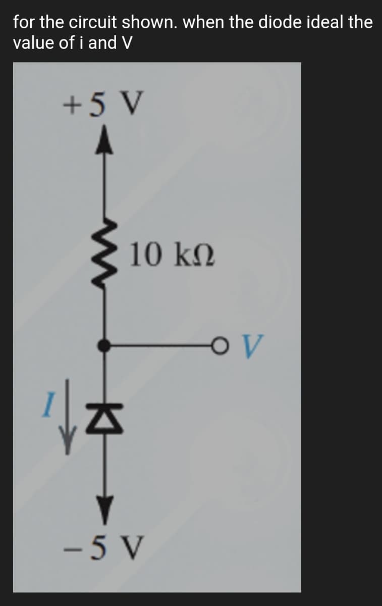
for the circuit shown. when the diode ideal the value of i and V +5 V 10 kN - 5 V


Q: helf guiz fast solutionz Determine the static or dc resistance of the commercially available diode…
A: According to question:
Q: 100 V Ideal diodes -100 V 2.2 k:
A:
Q: The zener diode shown in the circuit below will be conducting if the load voltage equals to |-5KSZ…
A: we need to find the load voltage in which zener diode is conducting.
Q: For the given circuit below, compute for the diode current. Si RL 8 k2 Vs 18 V-
A: In this question we will find current I..
Q: Produce a graph showing current I against the diode voltage VD. - Current (ID) vs Voltage (VD)
A: The above tabular information shows the characteristics of the diode in forward bias condition…
Q: For the circuit below with E = 10 V, R = 5800 N. Find the following: a) current in the circuit b)…
A:
Q: Given the circuit below, What is the output voltage in volts on the positive half cycle of the…
A: In this question we need to find a output voltage in positive half cycle.
Q: Determine the maximum value of V; that will maintain the Zener diode in the 'on' state given Vz=15V,…
A: Since, the given diode is in ON state then redrawing the circuit by replacing the diode by the given…
Q: Q2 A real diode for which the forward voltage drop is 0.7 V at 2.0 mA, what would be its current…
A:
Q: or the diode circuit shown, all diodes are identical with Is = 10-14 A. ind the value of the current…
A: Given: IS=10-14A and V0=2 V The current through the diodes is required
Q: roduce a graph showing current I against the diode voltage VD.
A: The given tables are shown below:
Q: Allow Vin to range from -10V to 10V and assume that the diodes are ideal. Determine the expression…
A:
Q: A diode has IS = 10−10 A and n = 2. (a) What is the diode voltage if the diode current is 40 A?
A: Given data: The diode voltage is: 40 A IS: 10-10 A The expression for the diode voltage is given…
Q: 4) A Zener Diode has an impedance of 15 ohm. What is the terminal voltage at 50 mA, if Vz = 4.7 at…
A: Brief description : A Heavily doped PN junction is known as a zener diode. Zener diode is used as a…
Q: For the network of figure shown below, determine and Sketch V. across the load 120 V RL resistance…
A: For positive half cycle, Output voltage is Vo=Vi5k×2k=25Vi For negative half cycle, 2kΩ and 3kΩ…
Q: For the circuit shown employing the ideal diodes, find the labeled current and voltage measured with…
A:
Q: Assume that the diode D1 is ideal and D2 has cut-in voltage of 0.3 V as given in the circuit below.…
A:
Q: Find current | if V = 5V and -5V when VB = 2V, R₁ = 2K, R₂ = 4K and the diode is ideal.
A: Given- Voltage, V =5 V and - 5V VB = 2 V R1 = 2 kohm R2 = 4 kohm Diode is ideal To find- Current for…
Q: Determine V, for the circuit shown below. Assume that the diode is ideal. 20 V -20 V +9
A: The given circuit is positive clamper with negative biased. In clamper circuit, peak to peak voltage…
Q: Determine the state of diode for the circuit shown and find ID, VD. Assume simplified model for the…
A: Given data : simplified model for the diode,
Q: Q12: Determine the current Vo of the figure below using the approximate equivalent model for the…
A:
Q: Find the voltages at V1 and V2. Consider as a practical diode. 6V +V 10k vi Si 6V Si +V v2 5k
A:
Q: Q1. For the circuit shown in Figure below find the maximum and minimum values of zener diode…
A: Using ohms law find the current through the source and current through the load. Using kcl find the…
Q: Given the circuit below, What is the output voltage in volts on the positive half cycle of the…
A: Solve for V0
Q: Determine the d.c. resistance of a diode at V=-20V if its reverse saturation current is 1 μA. (Take…
A:
Q: Determine whether the Diode is forward biased or not. If it is forward biased, find the current…
A:
Q: The Zener diode shown below, is specified to have Vz=2 Izk = 0.1mA, IzT = 17 mA, and r, = 14 N. Vcc=…
A: "Since you have posted a question with multiple subparts, we will solve the first three subparts for…
Q: Using the approximate characteristics for the si diode, determin Vo, Io and V
A: The given circuit diagram is shown below:
Q: D1 D, vo 1 kN 1 kN D2 D1
A: First we will find out relationship between input and output voltage . Then we will draw output…
Q: For the diode circuit to the right 8002 V V' 1002 b 40mA 0.001V a) To the left of points a and b,…
A:
Q: Assuming the ideal diode model (VON=0 V), calculate VOUT for the circuits in Figures (b) and (c) for…
A: For circuit a V1=0 v so this diode will be on but V2=5 v so this diode will be off as diode is deal…
Q: B. For the circuit shown, determine and sketch the output voltages (Vo). (All diodes are Silicon…
A:
Q: Using the approximate equivalent -2 model of a silicon diode and taking E=10 V and R=1k, what is the…
A: A diode is a two terminal electronic semiconductor device that conducts current primarily in one…
Q: 4-Using the ideal diode model of a silicon diode and taking E=10 V and R=1k, what is the value of…
A: Since the ideal diode model is taken we know the voltage at above which the diode conducts is the…
Q: 1. Describe in your own words the conditions established by forward and reverse bias conditions on a…
A: The diodes are made of semiconductor materials. Silicon and germanium are common semiconductors for…
Q: Using complete diode model and assuming that the forwyd resistance of thediode is 152 and a…
A:
Q: Solve for the diode current Ip and the voltage across the load R using the three diode models below:…
A: Given: V=5VRL=2.2kΩrd=15ΩVdiode=0.3V
Q: In testing a diode, if the red probe of an analog ohmmeter is tapped at the cathode while the black…
A: Diode: It is a semiconductor device. This will flow current in forwarding biased condition and does…
Q: With the given circuit below, if the input voltage is 10 volts peak-to-peak and the diode is…
A: In this question, we will find output voltage in negative half cycle of input...
Q: Calculate the voltage and current of the diode in the figure for each of the diode's models. In each…
A:
Q: ww R 15 V
A:
Q: Calculate the maximum-rated zener current, IZM, for the following 1/2-W zener diode VZ-5.6 V. b.…
A: In this question we will find maximum rated zener current for given diodes...
Q: Assuming an ideal diode model for all the diodes in the circuit below, Calculate the voltage across…
A: When a voltage is applied across circuit., Diode D2 & D3 Become Short -Circuited and Diode D1…
Q: 4) Determine vo and the required PIV rating of each diode for the configuration in the following…
A: Many electronic circuits require a rectified DC power supply to power various electronic basic…
Q: 3. Determine v o and the required PIV rating of each diode for the configuration of Figure below and…
A: In this question, Determine the output voltage Vo. Find the Peak inverse voltage of the diode.…
Q: Given the circuit below, What is the output voltage in volts on the negative half cycle of the…
A: Diode starts conducting when anode voltage is greater than cathode voltage and silicon diode…
Q: Si 10 V 102 本S
A:
Q: Determine the range of values of Vi that will maintain the Zener diode of in the "on" state. ... 220…
A: Zener diode maintains 20 volts when voltage across the zener diode exceeds 20 volts. Given maximum…
Q: Determine the current Io and voltage Vo of the figure below using the approximate equivalent model…
A:
Q: In a certain silicon diode, it was found that the diode current is 15mA when the diode voltage is…
A: Here, we have a Si diode at room temperature. The diode current, ID1=15 mA The diode voltage,…

Step by step
Solved in 2 steps with 2 images


- How is a solid-state diode tested? Explain.determine the current flowing through the zener diode having breakdown voltage of 5.6v of the circuit shown belowrefer to the circuit below, a) what is the current through R and 10k load? b) what is the actual current through the diode? c) what is the voltage across R and the 10k load?
- If a resistor is changed to a diode in an experimental circuit , is the superposition and homogeneity of the superposition principle still valid? If yes why is that?(a) Find I and V in the four circuits shown using the ideal diode model. (b) Repeat using the constant voltage drop model with Von = 0.65 V.For the circuit in the figure below, in which the diode has a value Vd = 0.7 V: Calculate the two values of Vout. Calculate the value of Vin that will cause Vout to change between the two levels found in part a). Sketch the signal Vout. Include values for time and voltages.
- Calculate diode forward current IF, diode voltage VF, and voltage drop across series resistor for three diode models (ideal, practical and complex).Assume diode forward resistance (dynamic resistance) r’d = 25Ω. Reverse leakage current IR = 75 nanoA with series resistance of RL = 100kΩ in reverse bias. Draw equivalent circuit diagrams of each model separately and plot corresponding I/V characteristics for each model.Briefly discuss the difference between Diode Piecewise-linear model, Simplified model, and Ideal device/ equivalent circuit. Study the diode specification sheets of a 1N4001 and 1N5401 diodes provided by the manufacturer and compare their difference. Give typical application of each. Discuss briefly how to test junction diode.determine the current I for the configuration shown below using approximate equivalent model for the diode
- The circuit shown is a voltage regulator circuit, it has a Zener diode with Vz=20V, the load resistance varies from 50 to 100 ohms and input voltage varies from 32V to 40V determine:- Value of R - P of Rmaxhelf guiz fast solutionz Determine the static or dc resistance of the commercially available diode of the figure shown below at a reverse voltage of -10 V. How does it compare to the value determined at a reverse voltage of -30 V?1. Briefly discuss the difference between Piecewise-linear model, Simplified model, and Ideal device. 2. Discuss briefly how to test junction diode. 3. Study the diode specification sheets of a 1N4001 and 1N5401 diodes provided by the manufacturer and compare their difference. Give typical application of each.