The zener diode shown in the circuit below will be conducting if the load voltage equals to |-5KSZ Vz =10v Yz=OV公 Vs


Q: Insert a diode into this circuit schematic in the correct direction to make it forward-biased by the…
A: The given circuit is,
Q: Sketch Vo for the network 100 V Ideal diodes -100 V 2.2 kQ 2.2 k2 2.2 k2
A: The diode is ON when the voltage across anode is more than the cathode voltage. It is known as…
Q: The output voltage V, of the following circuit during the positive half cycle considering ideal…
A:
Q: Q°: Assume ideal diode. Find the values of the labeled voltage and current. choice one only + 3 V +…
A: From the diode equivalent Circuit
Q: Discussion:- 1. Draw the forward and reverse characteristic of the diode on the same рaper.
A:
Q: Calculate vp (t) voltage of diode by using Modified Ideal Diode Model (Va=0.7V, V7=25mV, vi=0.7…
A:
Q: a) For the series diode configuration in the figure below, determine VD, VR and Ip. + Vp Si Ip 8 V…
A:
Q: a) For the series diode configuration in the figure below, determine VD, VR and Ip. + Vn IR Si Tp R…
A:
Q: In the voltage regulator circuit shown below the power rating of Zener diode is 400 mW. The value of…
A: Zener diode is heavily doped semiconductor that conduct in forward and reverse direction In forward…
Q: What is the value of reverse recovery charge developed in diode which is having the rate of fall of…
A:
Q: QUESTION 6 Determine whether each silicon diode in the following figure is forward biased (fb) or…
A: To determine the voltage across the diode by using practical model. As the both the terminal of…
Q: Using ideal diode model, the current I passing through the diode is equal to SKL I S1 lov 1.46mA…
A: Given circuit:
Q: For the given circuit, assuming an ideal diode, the value of current I will be: }25 kn 2.5 O a. 5 mA…
A: Given,
Q: For a certain 12 V zener diode, a 10 mA change in zener current produces a 0.1 V change in zener…
A: Zener diodes are diodes with high doping such that breakdown happens at some particular negative…
Q: 1. Sketch the output waveform Vo. 100 V Ideal diodes -100 V 2.2 ka 2.2 ka 2.2 k2
A:
Q: Solve the voltage across germanium diode of the given circuit below. 32 V lo2 AGe Si Vo 6.8 kohms 4…
A: Here two anti parallel Si and Ge diode Ge diode is reverse bia and si diode is forward bias cut in…
Q: d. Determine the minimum value of R1 to ensure that the Zener diode is in the “on" state. Rs 220 2…
A: Given
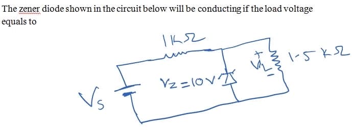
Q: The zener diode shown in the circuit below will be conducting if the load voltage equals to |-5KSZ…
A: If Applied voltage across zener diode is greater than It's Vz then zener diode will conduct in…
Q: For the network shown in Figure Q9, determine the range of V, that will maintain the Zener diode in…
A: Zener diode is heavily doped semiconductor that conduct in forward and reverse direction In forward…
Q: 4) Determine vo and the required PIV rating of each diode for the configuration in the following…
A:
Q: 06: - Find the following for the circuit shown below D.C output voltage 1) Rectification efficiency…
A: " Since you have posted a question with multiple subparts, we will solve the first three subparts…
Q: 1. Determine the range of V; that will maintain V, at 8V and not exceed the maximum power rating of…
A:
Q: Determine v, Epk+ Ideal R E Epk- Note: Diode is ideal. Replace diode with short when FB.
A:
Q: 100 V Sketch Vo for the network Ideal diodes -100 V 2.2 k2 2.2 ka 22 ka
A: The diode is ON when the voltage across anode is more than the cathode voltage. It is known as…
Q: R QUESTION #1. For the Zener diode network of figure below, if R = 1 k, RL = 5 kN, Vị = 24 V, Vz =…
A:
Q: R1 D1 D2 10 kQ V1 5 V +\V2 5V Vout Vin R3 10 kQ R2 10 kn
A:
Q: 2. A certain zener diode has a maximum power rating of 300 mW at 40 deg C and a derating factor of…
A: It is given that: PD=300 mWderating factor=1.4 mWdegT1=40 °CT2=80 °C
Q: Oʻ: Assuming the ideal diode model (VOn=0 V), calculate VoUT for the circuits in Figures (b) and (c)…
A: So for circuit b V1=0v so this diode will be off but V2=5v so this diode will be on so Voutb is 5v
Q: AV,= 50 mV IzK - 10 mA Alz= 5 mA 15 mA IR Figure 5
A:
Q: Using the load-line methodology, please find the operating point of the Zener diode of the following…
A: Diode- Diode means uni-directional flow of current, that's why to convert Ac to Dc voltage we use…
Q: Figure Q7 8. For the network shown in Figure Q8, determine the range of R that will maintain the…
A: Given, Rs=250ΩVi=20 VVz=10 VIzm=30 mA
Q: Question 2: For the circuit shown below, the diode cut in voltage is V70.6 V. Ipt Vo Ipa 1) Plot Vo…
A:
Q: Assuming the ideal diode model (VON=0 V), calculate VoUT for the circuits in Figures (b) and (c) for…
A:
Q: What is the value of reverse recovery charge developed in diode which is having the rate of fall of…
A: Given: Rate of fall of diode current, dIrrdt=34.7 A/μs Reverse recovery time, trr=5.6 μs
Q: 5) For the Zener diode network given below, determine VR, Iz, and Pz. 3 ka Vz = 10 v 16 V Py = 30 mw
A:
Q: The ezener diode shown in the circuit below will be conducting if the load voltage equals to |ト52 Vz…
A:
Q: а) i) Using the characteristics of the diode below determine Ip and V, for the circuit of given…
A: From the given circuit arrangement we can say that silicon diode is forward biased and it is…
Q: Solve the current flowing to germanium diode of the given circuit below. 32 V lo2 Ge Si O Vo 6.8…
A:
Q: Sketch Vo for the network 100 V Ideal diodes -100 V 2.2 k2 2.2 k2 2.2 k2
A: The diode is ON when the voltage across anode is more than the cathode voltage. It is known as…
Q: 1. Determine the range of V; that will maintain V, at 8V and not exceed the maximum power rating of…
A:
Q: O': Assuming the ideal diode model (VoN=0 V), calculate VoUT for the circuits in Figures (b) and (c)…
A:
Q: 1:Assuming the ideal diode model (VoN=0 V), calculate VOUT for the circuits in Figures (b) and (c)…
A: So for circuit a V1=0v so this diode will be off but V2=5v so this diode will be off so Vout is 5v…
Q: The diodes in the circuit are all Silicon with forward voltage of 0.7 V. If R1 = 14N and R2 = 140,…
A: Given circuit
Q: Calculate the maximum-rated zener current, IZM, for the following 1/2-W zener diode VZ-5.6 V. b.…
A: In this question we will find maximum rated zener current for given diodes...
Q: Q': Assuming the ideal diode model (VON=0 V), calculate VoUT for the circuits in Figures (b) and (c)…
A: B In the first circuit diagram that is be it is a logic to input or gate . It means here output…
Q: (B) Calculate the current through the zener diode for the given values of load resistance in this…
A:
Q: 2) a) For the given diode network, maximum amplitude of input voltage V,=40 is applied to the…
A: Given Input voltage=40 V
Q: Q1/ a- Using the characteristics of Figure below, determine Ip, Vp, VR for the following circuit: +…
A:
Q: Determine whether each silicon diode in the following figure is forward biased (fb) or reversed…
A: Suppose voltage across diode is VD Here, Cathode voltage is more than anode voltage so diode will be…
Q: Plot the current flowing through R as a function of Vin for the circuit Assume a constant-voltage…
A:

Step by step
Solved in 2 steps


- A diode is fabricated with NA >>ND. What value of doping is required on the lightly doped side to achieve a reverse-breakdown voltage of 750 V if the semiconductor material breaks down at a field of 300 kV/cm?A given diode, with n = 1, conducts 5mA with a junction voltage of 0.7, what is its saturation current Is ?, What current will flow in this diode if the junction voltage is raised to 0.71V?Sketch the transfer characteristic vo versus vi for the limiter circuit shown below. All diodes begin conducting at a forward voltage drop of 0.5V and have of 0.7V when fully conducting at 1mA.
- A silicon diode has a reverse saturation current of 50nA at room temperature (25degrees centigrade). If the operating temperature is raised by 50-degrees centigrade, what is now the reverse saturation current?for each circuit in the figure asume ideal diodes and Vi = 15 Vp, frecuency= 2kHz, find Vo and a picture of the waveform limiting it in magnitude and time.A diode with a voltage drop in the forward direction of 0.7V at 1.0mA and n = 1, what is the value of the current if it operates at 0.5V?
- Assuming the practical model, what PIV rating is required for the diode? The transformer is specified to have a 12 Vrms secondary voltage for the standard 110 V across the primary. (2nd Approximation)determine the current flowing through the zener diode having breakdown voltage of 5.6v of the circuit shown belowDetermine the conduction condition of the ideal diode in the circuit shown in the figure. (y=4)