For the composite beam shown in the figure below, determine the maximum stresses in steel and aluminum, L = 20 (a+b). 200 mm Al. 350 W(kn/m)=4 b(mm)=D40 a(mm)=80 (a), (b) and (w) are given in the table below.
For the composite beam shown in the figure below, determine the maximum stresses in steel and aluminum, L = 20 (a+b). 200 mm Al. 350 W(kn/m)=4 b(mm)=D40 a(mm)=80 (a), (b) and (w) are given in the table below.

Mechanics of Materials (MindTap Course List)
9th Edition
ISBN:9781337093347
Author:Barry J. Goodno, James M. Gere
Publisher:Barry J. Goodno, James M. Gere
Chapter9: Deflections Of Beams
Section: Chapter Questions
Problem 9.10.5P: A weight W = 4000 lb falls through a height h = 0.5 in, onto the midpoint of a simple beam of length...

Related questions
Question
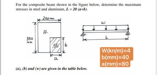
Transcribed Image Text:For the composite beam shown in the figure below, determine the maximum
stresses in steel and aluminum, L = 20 (a+b).
200mm
Al.
350
St6
W(kn/m)=4
b(mm)=40
a(mm)=80
(a), (b) and (w) are given in the table below.
Expert Solution
This question has been solved!
Explore an expertly crafted, step-by-step solution for a thorough understanding of key concepts.

Step by step
Solved in 2 steps

Knowledge Booster


Learn more about
Need a deep-dive on the concept behind this application? Look no further. Learn more about this topic, mechanical-engineering and related others by exploring similar questions and additional content below.Recommended textbooks for you
Mechanics of Materials (MindTap Course List)
Mechanical Engineering
ISBN:
9781337093347
Author:
Barry J. Goodno, James M. Gere
Publisher:
Cengage Learning
Mechanics of Materials (MindTap Course List)
Mechanical Engineering
ISBN:
9781337093347
Author:
Barry J. Goodno, James M. Gere
Publisher:
Cengage Learning