For the cross-section shown in Figure 2, determine the location of the shear center (e ?) 100mm 10mm V 6mm 190mm Shear Center e 10mm Figure 2
For the cross-section shown in Figure 2, determine the location of the shear center (e ?) 100mm 10mm V 6mm 190mm Shear Center e 10mm Figure 2

Mechanics of Materials (MindTap Course List)
9th Edition
ISBN:9781337093347
Author:Barry J. Goodno, James M. Gere
Publisher:Barry J. Goodno, James M. Gere
Chapter6: Stresses In Beams (advanced Topics)
Section: Chapter Questions
Problem 6.9.7P: The cross section of a slit square tube of constant thickness is shown in the figure. Derive the...

Related questions
Question
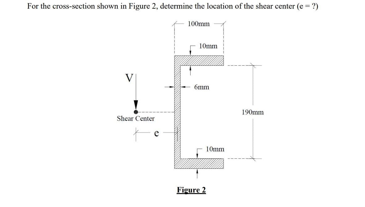
Transcribed Image Text:For the cross-section shown in Figure 2, determine the location of the shear center (e =
100mm
10mm
V
6mm
190mm
Shear Center
e
10mm
Figure 2
Expert Solution
This question has been solved!
Explore an expertly crafted, step-by-step solution for a thorough understanding of key concepts.

Step by step
Solved in 2 steps

Knowledge Booster


Learn more about
Need a deep-dive on the concept behind this application? Look no further. Learn more about this topic, mechanical-engineering and related others by exploring similar questions and additional content below.Recommended textbooks for you
Mechanics of Materials (MindTap Course List)
Mechanical Engineering
ISBN:
9781337093347
Author:
Barry J. Goodno, James M. Gere
Publisher:
Cengage Learning
Mechanics of Materials (MindTap Course List)
Mechanical Engineering
ISBN:
9781337093347
Author:
Barry J. Goodno, James M. Gere
Publisher:
Cengage Learning