What is the shear in member BC to the nearest 0.1k? L1 = 7 ft L2 = 8 ft L3 = 18 ft P = 8 k Pc = 9 k PC L3 B L2 L1 A
What is the shear in member BC to the nearest 0.1k? L1 = 7 ft L2 = 8 ft L3 = 18 ft P = 8 k Pc = 9 k PC L3 B L2 L1 A

Mechanics of Materials (MindTap Course List)
9th Edition
ISBN:9781337093347
Author:Barry J. Goodno, James M. Gere
Publisher:Barry J. Goodno, James M. Gere
Chapter6: Stresses In Beams (advanced Topics)
Section: Chapter Questions
Problem 6.10.17P

Related questions
Question
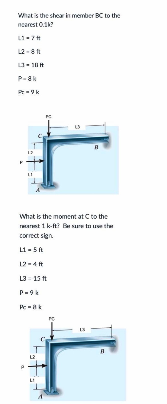
Transcribed Image Text:What is the shear in member BC to the
nearest 0.1k?
L1 = 7 ft
L2 = 8 ft
L3 = 18 ft
P = 8 k
Pc = 9 k
PC
L2
L1
What is the moment at C to the
nearest 1 k-ft? Be sure to use the
correct sign.
L1 = 5 ft
L2 = 4 ft
L3 = 15 ft
P = 9 k
Pc = 8 k
PC
L3
В
L2
L1
A
Expert Solution
This question has been solved!
Explore an expertly crafted, step-by-step solution for a thorough understanding of key concepts.

Step by step
Solved in 2 steps with 2 images

Knowledge Booster


Learn more about
Need a deep-dive on the concept behind this application? Look no further. Learn more about this topic, mechanical-engineering and related others by exploring similar questions and additional content below.Recommended textbooks for you
Mechanics of Materials (MindTap Course List)
Mechanical Engineering
ISBN:
9781337093347
Author:
Barry J. Goodno, James M. Gere
Publisher:
Cengage Learning
Mechanics of Materials (MindTap Course List)
Mechanical Engineering
ISBN:
9781337093347
Author:
Barry J. Goodno, James M. Gere
Publisher:
Cengage Learning