For the feedback circuit in fig(2): What is the F.B. topology Draw the basic amplifier without F.B. Calculate A, B, D, Ar, and Ave.
For the feedback circuit in fig(2): What is the F.B. topology Draw the basic amplifier without F.B. Calculate A, B, D, Ar, and Ave.

Power System Analysis and Design (MindTap Course List)
6th Edition
ISBN:9781305632134
Author:J. Duncan Glover, Thomas Overbye, Mulukutla S. Sarma
Publisher:J. Duncan Glover, Thomas Overbye, Mulukutla S. Sarma
Chapter12: Power System Controls
Section: Chapter Questions
Problem 12.3P

Related questions
Question
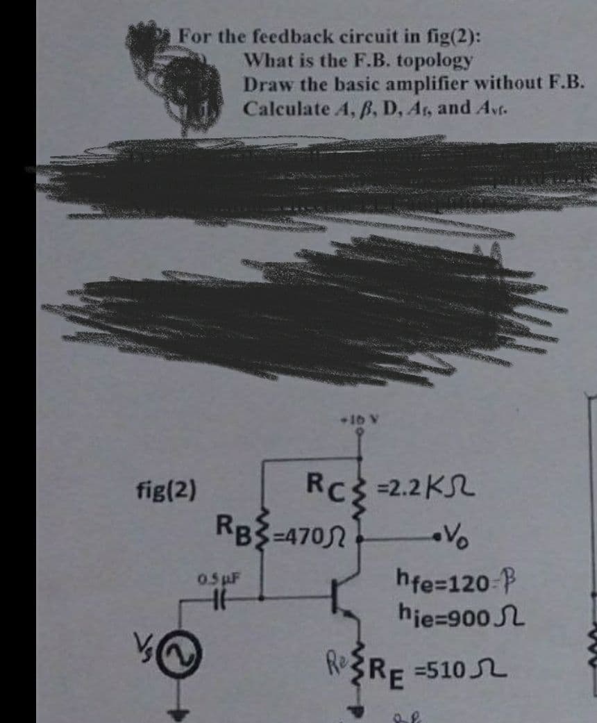
Transcribed Image Text:For the feedback circuit in fig(2):
What is the F.B. topology
Draw the basic amplifier without F.B.
Calculate A, B, D, Ar, and Avf.
fig(2)
RB-470
0.5 µF
HH
+16 V
RC = 2.2K
RC²
Re
hfe=120-
hie=900
=510
RE
Expert Solution
This question has been solved!
Explore an expertly crafted, step-by-step solution for a thorough understanding of key concepts.

Step by step
Solved in 4 steps with 20 images

Knowledge Booster


Learn more about
Need a deep-dive on the concept behind this application? Look no further. Learn more about this topic, electrical-engineering and related others by exploring similar questions and additional content below.Recommended textbooks for you
Power System Analysis and Design (MindTap Course …
Electrical Engineering
ISBN:
9781305632134
Author:
J. Duncan Glover, Thomas Overbye, Mulukutla S. Sarma
Publisher:
Cengage Learning
Power System Analysis and Design (MindTap Course …
Electrical Engineering
ISBN:
9781305632134
Author:
J. Duncan Glover, Thomas Overbye, Mulukutla S. Sarma
Publisher:
Cengage Learning