For the following circuit in the figure below consider the direction of the current given. Determine ɛ ( in units of V) when I = 0.50 A and R = %3D 30.1 Q. R 2R 2R Select one: A. 90.3 В. 20.0 С. 15.1 D. 60.2 O E. 75.2
For the following circuit in the figure below consider the direction of the current given. Determine ɛ ( in units of V) when I = 0.50 A and R = %3D 30.1 Q. R 2R 2R Select one: A. 90.3 В. 20.0 С. 15.1 D. 60.2 O E. 75.2

Chapter14: Inductance
Section: Chapter Questions
Problem 55P: How long after switch S1 is thrown does it take the current in the circuit shown to reach half its...

Related questions
Question
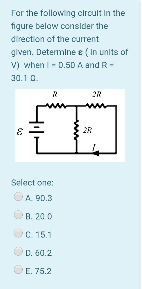
Transcribed Image Text:For the following circuit in the
figure below consider the
direction of the current
given. Determine ɛ ( in units of
V) when I = 0.50 A and R =
30.1 Q.
R
2R
2R
Select one:
A. 90.3
B. 20.0
C. 15.1
D. 60.2
O E. 75.2
Expert Solution
This question has been solved!
Explore an expertly crafted, step-by-step solution for a thorough understanding of key concepts.

Step by step
Solved in 3 steps with 2 images

Knowledge Booster


Learn more about
Need a deep-dive on the concept behind this application? Look no further. Learn more about this topic, physics and related others by exploring similar questions and additional content below.Recommended textbooks for you