For the footings shown in figure, calculate the increase in stress at point (A) at the depth of (3 m) under the surface of the ground.
For the footings shown in figure, calculate the increase in stress at point (A) at the depth of (3 m) under the surface of the ground.

Principles of Foundation Engineering (MindTap Course List)
8th Edition
ISBN:9781305081550
Author:Braja M. Das
Publisher:Braja M. Das
Chapter14: Sheet-pile Walls
Section: Chapter Questions
Problem 14.11P

Related questions

Question
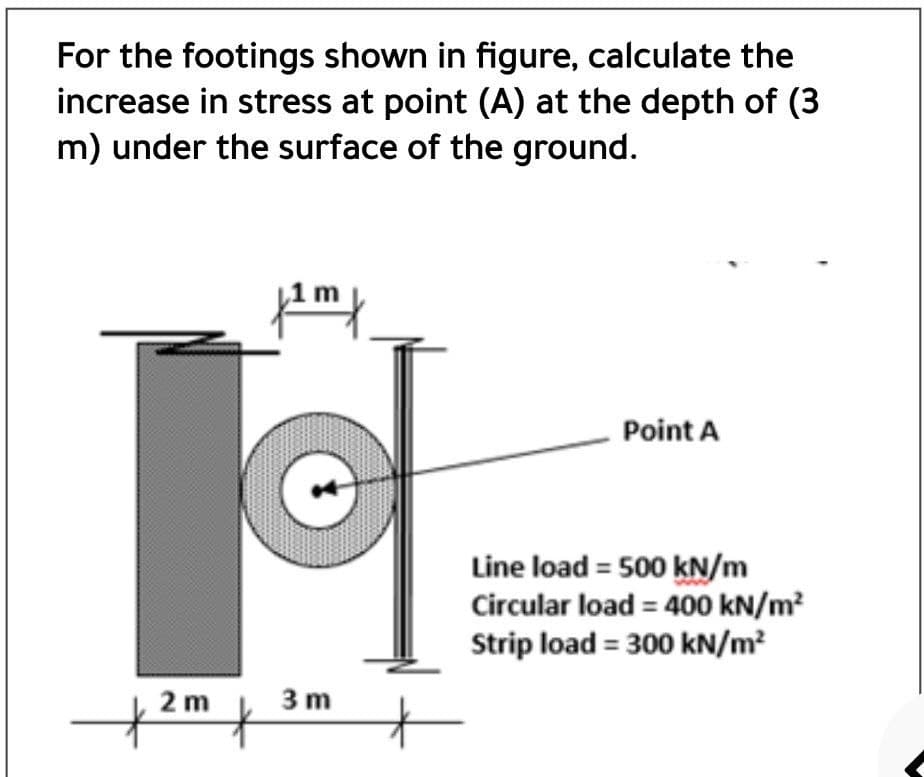
Transcribed Image Text:For the footings shown in figure, calculate the
increase in stress at point (A) at the depth of (3
m) under the surface of the ground.
Point A
Line load = 500 kN/m
Circular load = 400 kN/m?
Strip load = 300 kN/m?
2 m
3 m
Expert Solution
This question has been solved!
Explore an expertly crafted, step-by-step solution for a thorough understanding of key concepts.

Step by step
Solved in 4 steps with 4 images

Knowledge Booster


Learn more about
Need a deep-dive on the concept behind this application? Look no further. Learn more about this topic, civil-engineering and related others by exploring similar questions and additional content below.Recommended textbooks for you
Principles of Foundation Engineering (MindTap Cou…
Civil Engineering
ISBN:
9781305081550
Author:
Braja M. Das
Publisher:
Cengage Learning

Fundamentals of Geotechnical Engineering (MindTap…
Civil Engineering
ISBN:
9781305635180
Author:
Braja M. Das, Nagaratnam Sivakugan
Publisher:
Cengage Learning

Principles of Foundation Engineering (MindTap Cou…
Civil Engineering
ISBN:
9781337705028
Author:
Braja M. Das, Nagaratnam Sivakugan
Publisher:
Cengage Learning
Principles of Foundation Engineering (MindTap Cou…
Civil Engineering
ISBN:
9781305081550
Author:
Braja M. Das
Publisher:
Cengage Learning
Fundamentals of Geotechnical Engineering (MindTap…
Civil Engineering
ISBN:
9781305635180
Author:
Braja M. Das, Nagaratnam Sivakugan
Publisher:
Cengage Learning
Principles of Foundation Engineering (MindTap Cou…
Civil Engineering
ISBN:
9781337705028
Author:
Braja M. Das, Nagaratnam Sivakugan
Publisher:
Cengage Learning