For the four bus system as shown in Fig. Determine the fault current when the fault takes place at bus no.2 with fault impedance Zr =0 p.u. The Subtransient reactance of the generators and positive sequence reactance of other elements are given. Assume prefault Votage Eth=1Z0° pu Generator X = j0.12p.u; Transmission line X = j0.26p.u; Transformer X = %3D j0.43p.u À Yz Y= Zn in pu Fault current Ir in p.u 625FC6C7-5514JPES 46 (Mc_1850jpg
For the four bus system as shown in Fig. Determine the fault current when the fault takes place at bus no.2 with fault impedance Zr =0 p.u. The Subtransient reactance of the generators and positive sequence reactance of other elements are given. Assume prefault Votage Eth=1Z0° pu Generator X = j0.12p.u; Transmission line X = j0.26p.u; Transformer X = %3D j0.43p.u À Yz Y= Zn in pu Fault current Ir in p.u 625FC6C7-5514JPES 46 (Mc_1850jpg

Power System Analysis and Design (MindTap Course List)
6th Edition
ISBN:9781305632134
Author:J. Duncan Glover, Thomas Overbye, Mulukutla S. Sarma
Publisher:J. Duncan Glover, Thomas Overbye, Mulukutla S. Sarma
Chapter14: Power Distribution
Section: Chapter Questions
Problem 14.8P

Related questions
Question
Solve it fast plz
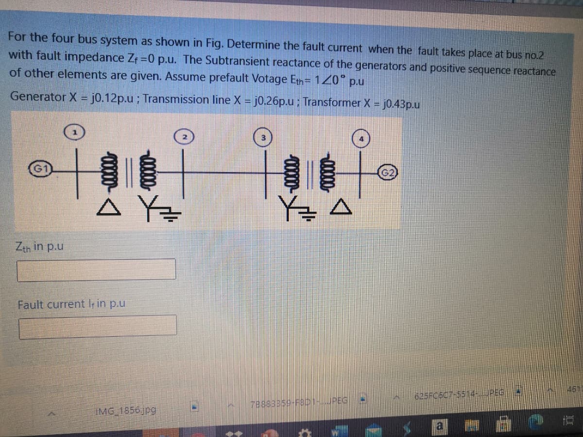
Transcribed Image Text:For the four bus system as shown in Fig. Determine the fault current when the fault takes place at bus no.2
with fault imnpedance Zr -0 p.u. The Subtransient reactance of the generators and positive sequence reactance
of other elements are given. Assume prefault Votage En= 120* p.u
Generator X = j0.12p.u ; Transmission line X = j0.26p.u; Transformer X =
j0 43p.u
A Y=
Y글 스
Zin in p.u
Fault current k in p.u.
461
625FC6C7-5514JPEG
(MG,1856jpg|
00000-
000
Expert Solution
This question has been solved!
Explore an expertly crafted, step-by-step solution for a thorough understanding of key concepts.

Step by step
Solved in 3 steps with 2 images

Knowledge Booster


Learn more about
Need a deep-dive on the concept behind this application? Look no further. Learn more about this topic, electrical-engineering and related others by exploring similar questions and additional content below.Recommended textbooks for you
Power System Analysis and Design (MindTap Course …
Electrical Engineering
ISBN:
9781305632134
Author:
J. Duncan Glover, Thomas Overbye, Mulukutla S. Sarma
Publisher:
Cengage Learning
Power System Analysis and Design (MindTap Course …
Electrical Engineering
ISBN:
9781305632134
Author:
J. Duncan Glover, Thomas Overbye, Mulukutla S. Sarma
Publisher:
Cengage Learning