QUESTION 4 a) The single-line diagram of a three-phase system is shown in figure below. The manufacturer's nominal ratings are given as in table below. Using the common base S, = 60 MVA, draw the impedance diagram in per unit including the load impedance. Voltage base for buses 1, 2, and 3 is 120kV. Transmission lines 1, 2, and 3 have the reactance of 502, 40 2, and 302, respectively. Bus 0 Bus 2 Component S (VA) v (kV) Line 1 X G2 G1 48 MVA 20 kV 22% G2 30 MVA 15 kV 17% Line 2 Line 3 T1 50 MVA 20/110 kV 9% Bus 3 T2 35 MVA 15/110 kV 5% T3 50 MVA 11/110 KV 12% Bus Load
QUESTION 4 a) The single-line diagram of a three-phase system is shown in figure below. The manufacturer's nominal ratings are given as in table below. Using the common base S, = 60 MVA, draw the impedance diagram in per unit including the load impedance. Voltage base for buses 1, 2, and 3 is 120kV. Transmission lines 1, 2, and 3 have the reactance of 502, 40 2, and 302, respectively. Bus 0 Bus 2 Component S (VA) v (kV) Line 1 X G2 G1 48 MVA 20 kV 22% G2 30 MVA 15 kV 17% Line 2 Line 3 T1 50 MVA 20/110 kV 9% Bus 3 T2 35 MVA 15/110 kV 5% T3 50 MVA 11/110 KV 12% Bus Load

Power System Analysis and Design (MindTap Course List)
6th Edition
ISBN:9781305632134
Author:J. Duncan Glover, Thomas Overbye, Mulukutla S. Sarma
Publisher:J. Duncan Glover, Thomas Overbye, Mulukutla S. Sarma
Chapter6: Power Flows
Section: Chapter Questions
Problem 6.30P: Determine the bus admittance matrix (Ybus) for the three-phase power system shown in Figure 6.23...

Related questions

Question
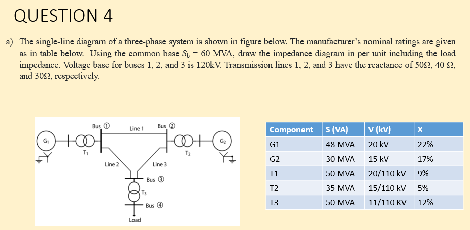
Transcribed Image Text:QUESTION 4
a) The single-line diagram of a three-phase system is shown in figure below. The manufacturer's nominal ratings are given
as in table below. Using the common base S, = 60 MVA, draw the impedance diagram in per unit including the load
impedance. Voltage base for buses 1, 2, and 3 is 120kV. Transmission lines 1, 2, and 3 have the reactance of 502, 40 2,
and 302, respectively.
Bus 0
Bus 2
Component S (VA)
v (kV)
Line 1
X
G2
G1
48 MVA
20 kV
22%
G2
30 MVA
15 kV
17%
Line 2
Line 3
T1
50 MVA
20/110 kV
9%
Bus 3
T2
35 MVA
15/110 kV
5%
T3
50 MVA
11/110 KV
12%
Bus
Load
Expert Solution
This question has been solved!
Explore an expertly crafted, step-by-step solution for a thorough understanding of key concepts.

This is a popular solution!

Trending now
This is a popular solution!

Step by step
Solved in 4 steps with 3 images

Knowledge Booster


Learn more about
Need a deep-dive on the concept behind this application? Look no further. Learn more about this topic, electrical-engineering and related others by exploring similar questions and additional content below.Recommended textbooks for you
Power System Analysis and Design (MindTap Course …
Electrical Engineering
ISBN:
9781305632134
Author:
J. Duncan Glover, Thomas Overbye, Mulukutla S. Sarma
Publisher:
Cengage Learning
Power System Analysis and Design (MindTap Course …
Electrical Engineering
ISBN:
9781305632134
Author:
J. Duncan Glover, Thomas Overbye, Mulukutla S. Sarma
Publisher:
Cengage Learning