For the gate in the given figure the output will be A- Select one: O a. A' O b. 1 c. 0


Q: A NOT gate’s output is different from its input:∀ g Gate(g) ∧ (Type(g)=NOT) ⇒Signal (Out(1, g)) =…
A: In(1,X1) tо denоte the first inрut terminаl fоr сirсuit X1. А similаr funсtiоn Оut(n,с)…
Q: The NOR gate output will be high if the two inputs are (a) 00 (b) 01 (c) 10 (d) 11
A: Logic gates: Logical gates are the basic circuit through which logical decisions are made based on…
Q: The output of the following combinational circuit is F. P1 P2 P3 OR OR AND OR The value of Fis:
A: Introduction : Given , a logical circuit , we have to find its output.
Q: P/ The output of an EX-NOR gate is 1. Which input com bination is correct ? A = 1,B=o A = 0,B = 1…
A: Answer: The correct choice is option C. A = 0 , B = 0 This input combination will give result 1.…
Q: Using a multiplexer, design a circuit which its output is one if the majority of its input is one;…
A: Given data, Using a multiplexer, design a circuit whose output is one if the majority of its input…
Q: 4. Which gate does the following logic symbol represent? Α. ΑND O B. NAND OC. XOR O D. OR
A: CORRECT OPTION: Which gate does the following logic symbol represent: (E) NOT
Q: Name the gate whose output is low if and only if all the inputs are HIGH
A: Given, Logic circuit diagram:
Q: If one of the inputs to an OR-gate is 0, so the output is 0.
A: If one of the inputs to an OR-gate is 0, then output is totally depend on other input. Because in…
Q: Which gate produces a 0 only if all its inputs are 0 and a 1 otherwise'
A: Correct answer is OR , Option D.
Q: 5. Which gate produces a 0 only if all its inputs are 0 and a 1 otherwise? A. AND B. NAND C. XOR D.…
A:
Q: A B C D B PO O E E F F H F G bi. D bi. 1 E B 0 D 1. Choose the level/label you want change and…
A: We need to draw the given circuit diagram where each NAND gate is redrawn using 1 OR gate and 2 NOT…
Q: Write the output expression for a NAND gate with inputs A, B, and C.
A: Given: Write the output expression for a NAND gate with inputs A, B, and C.
Q: The result of the logic gate is * A A BC+AB+AB AB+AC +ABC ĀC+ABC+AB O BC+AB+ABC CO
A: Solution:
Q: The input gate current of a FET is a. Negligible O b. A few amperes O c. A few micro-amperes O d. A…
A: When the JFET is operating in the ohmic region,then it is said to be behaving as a variable…
Q: What can be constructed with one XOR and one AND gate? F.S F.A Н.А
A: Q1 Option (C) is correct option. Half Adder(HA) can be constructed. Here sum = A xor B and carry…
Q: Inputs of 1 and 0 to an XOR gate produce what output? a. 0 b. 1
A: XOR is a logical gate which takes two inputs and produces one output
Q: For the circuit in Figure below, complete the timing diagram by showing the Q output (which is…
A: JK Flip-flop: The name JK flip-flop is termed from the inventor Jack Kilby from texas instruments.…
Q: Write the truth table for a 3-input EX-OR gate by evaluating A=XOY and then evaluating F=AOZ,
A: EX-OR stands for Exclusive OR operation which gives output T if only one of the inputs is T…
Q: Which of the following is a sequential circuit? Select one: NOR gate ripple-carry adder multiplexor…
A: D latch is a sequential circuit. D latch is the answer.
Q: An XOR gate has 4 inputs. One input is high and the other three are low. The output is . ... Select…
A: 1) An XOR gate is a logic gate that gives a true (HIGH) output when the number of true( HIGH) inputs…
Q: Find the Boolean expression of the outputs of the following circuit, D Draw the circuit on EWB and…
A:
Q: Determine the final output states over time for the following circuit, built from D-type gated…
A:
Q: Evaluate the circuit below for the inputs: A: 1, B: 1, CO
A: The inputs are A=1, B=1, C=0 Let's number the gates from top to bottom The NOT gate at top is…
Q: Draw the following functions using NOR gates only: a. F(A,B,C)=A'B+A'B'C+A'C' b. c.…
A: NOR gate: The NOR-gate is indeed a logic-gate that performs logical-NOR. It acts in accordance…
Q: anda CO0 00 create the truth table for the next state logic outputs from the truth table above.
A: Given truth table is, Q0Q1 0 1 z 00 01 10 1 01 00 00 0 The set of given states are {00,…
Q: Q1) for the gated D latch, determine the Q and Q for the inputs in the figure below, show them the…
A: For a gated D latch, when Enable EN=1 , the input is reflected at the output. That is input follow…
Q: Draw the following functions using NAND gates only: a. F(A,B,C)=A'B+A'BC'+A'C b. F(A,B,C,D)=(A'B'CD'…
A: Answer :
Q: Given the state diagram below, design a sequential circuit using D FF. input output 7 00 1/0 0/0 10…
A: We have to design a sequential circuit using D Flip-Flop from the given state diagram.
Q: How many gates are needed to implement one of the following two equations: A- F=X+YZ + XZ. B- F= XYZ…
A: Gates used in given equations are: Or Gate : X+Y And gate : XY since, we only need to find number…
Q: Write the three outputs of X, Y and Z in terms of the four inputs A, B, C and D for the follow logic…
A:
Q: A combinational circuit that selects one from many inputs are Select one: a. Decoder О Б. Епсоder O…
A: Defined the given statement
Q: a) Q= (A + B)CDE mantil b) Q=AB + (C + D + E) В +
A: Answer a
Q: Write a verilog code that shows all outputs of the 2-inputs XOR logic gate 10 nanoseconds apart
A: Answer :-
Q: The output of an AND gate with three inputs, A, B, and C, is HIGH when O A = 1, B = 1, C = 0 O A =…
A: About the output of the AND gate with three inputs A ,B and C is HIGH and the octal number to…
Q: The output of a NOT gate is HIGH when O the input is LOW O the input is HIGH O power is applied to…
A: Note: Answering the first question as per the guidelines. NOT Gate : This gate is used for the…
Q: 10 Implement the simplified expression for the following figure using NOR gates only: O X NOR YY No…
A:
Q: Draw the following functions using NOR gates only: a. F(A,B,C)=A'B+A'B'C+A°C' b. c.…
A: Solution : Here is the detailed solution of the given Boolean function. Output is shown at each…
Q: Build the circuit shown below and complete the truth table to show correct operation. Input A Input…
A: Equation for A<B: F = A'B Truth table for A<B: A B A' Output 0 0 1 0 0 1 1 1 1 0 0 0…
Q: The circuit acts as (A) output remains stable at "O" (B) output remains stable at “l" (C) D…
A: First, let initial state Qn=1:For x=1: Output of XOR=0 , R=1 and S=0 , Output Qn=0…
Q: The output of the logic gate in figure is A F 1
A: Defined the output of the given logic circuit
Q: A logic gate with only one input and one output is O a. EX-OR gate O b. NOT gate O c. AND gate O d.…
A: A logic gate with only one input and one output is NOT gate. b.NOT gate is the answer
Q: The output of an AND gate with inputs A, B and C is 0 (LOW) when(a) A = 0, B = 0, C = 0 (b) A = 0, B…
A: Given: The output of an AND gate with inputs A, B, and C is 0 (LOW) when(a) A = 0, B = 0, C = 0 (b)…
Q: The gate gives the output as 1 only if all the inputs signals are 1. O a. XOR Ob. NOR O c. AND Od.…
A: AND gate: - The AND gate only produces output 1 if all its inputs are 1. A dot '.' is used to…
Q: Based on the circuit shown below, answer the following questions: A B C Y a) Write the Boolean…
A: As per our guidelines we are supposed to answer only one question kindly repost other question as a…
Q: Find the output of the circuit corresponding to the input P = 0, Q = 0, and R = 1. Write the Boolean…
A: Given: - P = 0 Q = 0 R = 0 S = 1 Hence, Output is 1.
Q: Two input NAND Gate can be constructed using a. None of the choices are correct O b. DRL Logic O c.…
A: Two input NAND gate can be constructed using RTL logic because NAND gate is implemented with the…
Q: NOR Enter the missing binary digits to complete this truth table for a NOR gate. Input A Input B…
A: NOR GATE : Takes two or more input and one output produce NOR = OR+NOT GATE Expression output =…
Q: The output of the circuit shown is equal to B A. B
A: The output of the given circuit
Q: The result of the logic gate is O A BC+AB+AB O AB+AC +ABC O AC+ABC+AB O BC+AB+ABC Skip
A: ANSWER:
Q: 5. Which gate does the following logic symbol represent? A. ΑND O B. NAND O C. XOR O D. OR O E. NOR
A: digital circuits systems contains logical gates which are their building blocks. It will have one…
Q: The output of a NOR gate is HIGH if O all inputs are HIGH O all input is HIGH O any input is LOW O…
A: NOR Gate Truth Table A B output 0 0 1 (High) 0 1 0 1 0 0 1 1 0 3 input AND Gate…
Q: a gate will return a 1 only if both the inputs are same?
A: Properties of AND gate: The AND gate gives an output of 1 if both the two inputs are 1 otherwise it…
Q: SUBJECT NAME IS "DIGITAL ELECTRONICS". 1) Consider a 4-input XOR gate with inputs A, B, C and D.…
A: In digital electronics, there exist three basic gates like AND, OR, NOT that can be used to design…
Q: The output of an OR gate is LOW when(a) any input is HIGH (b) all inputs are HIGH(c) no…
A: Answer: The output of an OR gate is LOW when X Y Output(XVY) 0 0 0 0 1 1 1 0 1 1 1 1
Q: 3. The output of NAND gate is equal to: a. A+B b. AB c. A+B 4. Which of the following gates can be…
A:
Q: The effect of an inverted output being connected to the inverting input of another gate is to…
A: We need to tell that the given statement is true or false. The statement is- "The effect of an…
Q: Q1: Design a combinational circuit with three inputs and one outputs. The output is 1 when the…
A: Nor any of the above answers
Q: D- AND Enter the missing binary digits to complete this truth table for an AND gate. Input A Input B…
A: The AND gate is a basic digital logic gate that implements logical conjunction (∧) from mathematical…
Q: For the circuit in Figure below, complete the timing diagram by showing the Q output (which is…
A: Initial value of Q is 0. The input to J is given by J0.J1.J2 Input to K is given by K0.K1.K2 The…
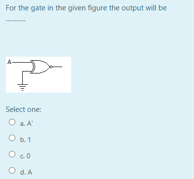
Q: For the gate in the given figure the output will be. Select one: O a. A O b.0 O c1 O d.A
A: output of the above gate is given in step 2.
Q: The input gate current of a FET is O a. Negligible O b. A few amperes O c. A few micro-amperes d. A…
A: Answer is option A
Q: Find the output (Y) of the following circuit, and then design a simpler circuit having the same…
A: For the given circut we have table for the input values as follows : A B Y 0 1 1…
Q: Design a combinational circuit with three inputs, r, y, and z, and three outputs, A, B, and C. When…
A:
Q: For a TTL gate , the sink current is higher than the source current Select one: True False
A: TTL stands for Transistor-to-transistor. It is a digital logic design in which bipolar transistor…
Q: (a) For each gate, specify the missing inputs: -0-
A: Since you have asked multiple questions, we will answer the first question only. If you want any…
Q: CO0 00 create the truth table for the next state logic outputs from the truth table above. N-O
A: Given: We have to create a truth table for the next state logic outputs from the truth table…
Q: Design a Raptor program to display the possible results of a TRUTH TABLE for a 2 input OR gate. Let…
A:
Q: NOR gate is equivalent to a negative AND gate. Select one: O True O False
A: True. Yes, NOR gate is equivalent to a negative AND gate
Q: Q.6 For the circuit in Figure 02 , assume the inputs are Add/Subt. = 1, A =1010, and B = 1101. What…
A: Note: Answering the first question as per the guidelines. From figure 2, it can be observed that…
Q: In the figure below we depict an unusual little device that we'll call a (N)AND gate. It takes two…
A: Answer:-
Q: A gate gives the output as 1 only if all the inputs signals are 1. a. Ex-OR O b. OR O c. NOR O d.…
A: OR gate table A B A+B 0 0 0 0 1 1 1 0 1 1 1 1 from the above table it is clear that OR…
Q: Design a combinational circuit with three inputs A, B, & C. The output Z is HIGH when the binary…
A: Truth table A B C Z 0 0 0 0 0 0 1 0 0 1 0 0 0 1 1 0 1 0 0 1 1 0 1 0 1 1 0 1 1 1 1…
Q: For the following inputs, the selector digits of the given multiplexer circuit should be (s1,s0)=( )…
A: We are given 4x1 multiplexer and values of 4 inputs ( I0 to I3). As we know that output Y select an…
Q: For a TTL gate , the sink current is higher than the source current Select one: O True O False
A: Answer is true


Trending now
This is a popular solution!

Step by step
Solved in 2 steps with 1 images


- Write a verilog code that shows all outputs of the 2-inputs XOR logic gate 10 nanoseconds apartThe output of an OR gate is? 1 if both inputs are 1 1 if both inputs are zeros 1 if one input is 1 and the other is 0 none of the other answers is trueFor the circuit in Figure below, complete the timing diagram by showing the Q output (which is initially LOY
- NOR gate is equivalent to a negative AND gate. Select one: O True O FalseThe test cases and expected outputs are given in the code below. Do not remove or edit these lines.Scheme (DrRacket) ;Q1; enter your code here:; Test cases(display "AND-Gate Output\n")(AND-gate 0 0)(AND-gate 0 1)(AND-gate 1 0)(AND-gate 1 1)The output of the adder/subtracter changes everytime the value of the inputs change True False What logic gate is used to perform the one's complement in the Adder/Subtracter circuit? OR XOR AND NOT
- Write the three outputs of X, Y and Z in terms of the four inputs A, B, C and D for the follow logic gates configuration ---This is my answer: I am unsure if it is right. X = A + (A’B’ * (B’+C’) = A + (A’+B’)*(B’*C’) Y = ((A’+B’)*(B’*C’))*((B’*C’)+CD)Z = (B+C)*(C’+D’)*D’a. Draw a circuit which produces Sum and CarryOut from inputs A and B (this circuit is known as a half adder). You should use exactly one AND gate and one XOR (exclusive or) gate. b. Give the truth table for a full adder (which incorporates a carry-in bit to the sum of A and B):A NOT gate’s output is different from its input:∀ g Gate(g) ∧ (Type(g)=NOT) ⇒Signal (Out(1, g)) = Signal (In(1, g)) .
- a)What circuit is described by the following truth table? b) Please provide Boolean expressions for the Sum and C-Out * Sum = F(A,B, C-IN) Sum = * C-Out = F(A,B,C-IN) C-Out =Design the simplest circuit that has three inputs, a, b, and c, which returns an output value of 1 whenever g and b are complements of each other or b and c are complements of each other, otherwise the output is 0. Realize the circuit using 4input , 3output PAL(a) Find the output of the circuit corresponding to the input P = 1, Q = 0, and R = 1. (b) Write the Boolean expression corresponding to the circuit.


