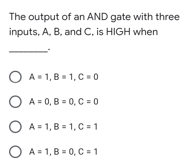
The output of an AND gate with three inputs, A, B, and C, is HIGH when O A = 1, B = 1, C = 0 O A = 0, B = 0, C = 0 O A = 1, B = 1, C = 1 O A = 1, B = 0, C = 1


Q: نقطة واحدة A synchronous state machine has two inputs (X1 and X2) and one output (Z). The…
A: 8
Q: The output of a logic gate is an inversion of the input. What type of logic gate is it?
A: The NOT gate is an electronic circuit that generates an inverted version of the input at its output.…
Q: Draw the circuit and obtain the truth table of the VHDL module below module SAM(a, b, c, M, S);…
A: We need to draw the circuit and obtain the truth table of the given VHDL module.
Q: A voltage amplifier with gain 3 dB is cascaded with an attenuator of attenuation (ratio) of 1/v2.…
A: Refer to step 2 for the answer.
Q: In a logic families, the amount of noise voltage that the digital circuit can tolerate without…
A: the amount of noise voltage that the digital circuit can tolerate without disturbing or causing an…
Q: Design a 4-input (A,B,C,D) digital circuit that will give at its output (X) a logic 1 only if there…
A: The truth table is shown below: Input A B C D Output…
Q: If a two-input logic gate produces an output of logic HIGH, only if both inputs are different, then…
A: Question If a two-input logic gate produces an output of logic HIGH, only if both inputs are…
Q: 5. Which gate produces a 0 only if all its inputs are 0 and a 1 otherwise? A. AND B. NAND C. XOR D.…
A:
Q: The basic gate whose output is the complement of the input is the a NOT gate. Ob. OR gate. oC AND…
A: Answer: NOT gate
Q: The basic gate whose output is the complement of the input is the ____________. a. AND gate.…
A: the question asks which gate will generate the result of the complement of its input.
Q: A NAND gate has inputs A and B. It's output is connected to both inputs of another NAND gate. An…
A: If inputs are A and B, then NAND is represented as (A.B)'
Q: A 2-input gate has inputs of A = 1 and B = 0. If the output is a '1', then the gate could be gate. O…
A: Gates
Q: Design and implement sequential digital circuit, with following specifications: It has one input X,…
A: Here, I have to provide a solution to the above question.
Q: 1. Draw the state diagram and state table for the following circuit: D. D. Clock X- Present state…
A: Solution: we make truth table: ============================================
Q: Consider an OAI321 static CMOS gate. (a) Draw the logic diagram (i.e. using AND/OR/INVERTER gates)…
A: Actually, logic gates are AND,OR,NOT,XOR
Q: A three input NOR gate gives a logic high outpl only when A One input is high B One input is low C…
A: the answer is an two input low
Q: For the following inputs, sketch the O/P of the following gates. 1. AND, 2. OR, 3. NAND, 4) Not for…
A:
Q: An asynchronous state machine has two inputs (X1 and X2) and one output (Z). The output is the same…
A: (A) 2 NOT gates
Q: Inputs of 1 and 0 to an XOR gate produce what output? a. 0 b. 1
A: XOR is a logical gate which takes two inputs and produces one output
Q: The minimum number of transistors required to implement a two input AND gate is
A: the minimum number of transistors required to implement a two input AND gate is
Q: Question 1 : Consider the following combinational circuit (3 inputs: A, B and C- 2 outputs: X and Y)
A:
Q: n XOR gate has 4 inputs. One input is high and the oth w. The output is .. ...... elect one: D a.…
A: Given:
Q: An XOR gate has 4 inputs. One input is high and the other three are low. The output is . ... Select…
A: 1) An XOR gate is a logic gate that gives a true (HIGH) output when the number of true( HIGH) inputs…
Q: An IC with two-input logic gate produce a output as HIGH, only if both the inputs are different is
A: An IC with two-input logic gate produce a output as HIGH, only if both the inputs are different.
Q: The operation F(X, Y, Z) = (!X + !Y + !Z) can be implemented with a single input signals and one…
A: Here in this question we have given a some boolean expression and we have asked to implement with…
Q: Present state Input Next state Output Output Flip-flop input functions A B X A B Y TA TB 0 0 0 0 1 0…
A:
Q: Given the following characteristic table of a new type of latch, design the circuit that implements…
A: We have seen throughout this section of the Electronics Tutorial in Sequential Logic that the…
Q: A three-input logic gate gives the output X shown below. The gate is a A В C X O three-input NOR…
A: As from figure above , we observed that whenever one or more input is 0 output becomes 1. also, when…
Q: Consider a 2 input NOR gate as shown below: VDD B OUT Which of the following represents the worst…
A: Answer: The inclusive NOR (Not-OR) gate has a logic level "1" output that only goes "LOW" to logic…
Q: A synchronous state machine has two inputs (X1 and X2) and one نقطة واحدة output (Z). The…
A: The solution to the given problem is below.
Q: An asynchronous state machine has two inputs (X1 and X2) and one output (Z). The output is the same…
A: Ans: An asynchronous state machine has two inputs(X1 and X2) and on output(Z). The output is same of…
Q: The output of a three input AND gate (with inputs A, B and C) is equal to 1 when O a. A=0, B=0, C=0…
A: The 3-input Logic AND Gate is given below: Symbol Truth Table 3-input AND Gate C B A Q…
Q: The output of a logic gate is 1 when all inputs are at logic 0.The output of a logic gate is 1 when…
A: Correct Answer:D
Q: Simplify the following functions and implement them with two-level NAND gate circuits: a. F(A,B,C,D)…
A: Simplifying using Laws of boolean algebra:boolean laws to be used in simplification:disribution :…
Q: Using a decoder and external gates, design the combinational circuit defined by the following three…
A: Decoder A decoder is a digital circuit that converts a code into a set of signals. A simple…
Q: Draw the circuit and det (а) Cin (b) Parasitic delay ( (c) Logical effort (g for the following…
A: The design of semiconductors is a complex array of choices between what is the best circuit topology…
Q: The output of an AND gate with inputs A, B and C is 0 (LOW) when(a) A = 0, B = 0, C = 0 (b) A = 0, B…
A: Given: The output of an AND gate with inputs A, B, and C is 0 (LOW) when(a) A = 0, B = 0, C = 0 (b)…
Q: QI) Design a combinational circuit with three inputs, A, B and Outputs, X,Y and Z. when the binary…
A: Truth Table is A B C X Y Z 0 0 0 0 1 0 0 0 1 0 1 1 0 1 0 1 0 0 0 1 1 1 0 1 1 0 0 1 1 0…
Q: An asynchronous state machine has two inputs (X1 and X2) and one output (Z). The output is the same…
A: Ans: An asynchronous state machine has two inputs(X1 and X2) and one output(Z). The output is same…
Q: Design and implement sequential digital circuit, with following specifications: It has one input X,…
A: the solution for the above-given question is given below:
Q: following combinational circuit (3 inputs: A, B and C- 2 outputs: X and Y) x1 B x1 C x1 x1 b- Redraw…
A: check further steps for the answer :
Q: The circuit below has a 2-to-4 decoder with active high outputs connected to a 4-to-1 MUX. Derive an…
A: Decoder:A binary code of n bits is capable of representing up to 2^n distinct elements of coded…
Q: A combinational circuit has 3 outputs F1, F2 and F3 F1 = xyZ+ xZ F2 = xỹ Z+X y F3 = x y z+ xy Design…
A: Decoder: A combinational circuit that converts n inputs lines into a maximum of 2n output lines.…
Q: A gate have two inputs (A, B) and one output (Y) is implemented using a 4 x 1 MUX as shown in the…
A: Introduction :
Q: The output of an OR gate is LOW when(a) any input is HIGH (b) all inputs are HIGH(c) no…
A: Answer: The output of an OR gate is LOW when X Y Output(XVY) 0 0 0 0 1 1 1 0 1 1 1 1
Q: A Full Adder Circuit is shown in Figure utilizing two Half Adders and an OR Gate. The major input…
A:
Q: (a) For each gate, specify the missing inputs: -0-
A: Since you have asked multiple questions, we will answer the first question only. If you want any…
Q: A synchronous state machine has two inputs (X1 and X2) and one output (Z). The relationship between…
A: Lets see the solution in the next steps
Q: Inputs D B A a 1 1 1 1 1 1 1 1 1 1 1 1 1 1 1
A: With the help of KMAP, first we will find out the boolean expression and then draw a logic diagram…
Q: An asynchronous state machine has two inputs (X1 and X2) and one output (Z). The output is the same…
A: Introduction: OR gate truth table: Input 1 Input 2 Output 0 0 0 0 1 1 1 0 1 1 1 1…

Step by step
Solved in 2 steps


- A Full Adder Circuit is shown in Figure utilizing two Half Adders and an OR Gate. The major input bits are A and B, the carry input is CIN, and the Sum and Carry Outputs are COUT, respectively. Design of Finite State Machine for the figure below Truth table: (Half adder) A B Sum Pi=A⊕B Carry, Gi=AB 0 0 0 0 0 1 1 0 1 0 1 0 1 1 0 1 Truth table: (Full adder) A B Ci Sum, S=A⊕B⊕Ci Carry, C0=AB+CiA⊕B 0 0 0 0 0 0 0 1 1 0 0 1 0 1 0 0 1 1 0 1 1 0 0 1 0 1 0 1 0 1 1 1 0 0 1 1 1 1 1 1Design the simplest circuit that has three inputs, a, b, and c, which returns an output value of 1 whenever g and b are complements of each other or b and c are complements of each other, otherwise the output is 0. Realize the circuit using 4input , 3output PALConstruct a 3-bit counter using three D flipflops and a selection of gates. The inputs should consist of a signal that resets the counter to 0, called reset, and a signal to increment the counter, called inc. Th e outputs should be the value of the counter. When the counter has value 7 and is incremented, it should wrap around and become 0.
- let consider 5 different outputs in combinational circuit/ Digital Logic Design For example x=1 y= 0 a =1 b= 1 c=0 Design a single output schema which take the 5 different outputs into a single 5 bit output Y[4:0] Y output will be for example 5 bits 10110Draw the circuit and obtain the truth table of the VHDL module below module SAM(a, b, c, M, S);input a,b,c;output M;output S;wire d,e,f;xor(S,a,b,c);and(d,~a,b);and(e,b,c);and(f,~a,c);or(M,d,e,f);endmoduleDraw a circuit that implements a 3-bit Adder that takes two 3-bit numbers as input, each on 3 input lines and outputs a 4 bit number on 4 output lines. You may use the Half Adder, the Full Adder and the following gates: NOT, AND, OR, XOR. Make sure to clearly label the interface wires on your diagram and the types of gates you use.
- Consider an OAI321 static CMOS gate.(a) Draw the logic diagram (i.e. using AND/OR/INVERTER gates)(b) Draw the transistor schematic (using NFET/PFETs)Design a combinational circuit with three inputs x, y, z, and three outputs a, b, and c. When the binary input is 0, 1,2, or 3 , the binary output is 1 greater than the input. When the binary input is 4, 5, 6, or 7, the binary output is one less than the input.Design a two-bit counter (sequential circuit) using falling edge triggered T-flipflops, with one input line x. When x= 1, the state of the circuit remains the same. When x = 0, the circuit goes through the state transitions byincrementing the state count, i.e., from 00 to 01, 01 to 10, 10 to 11, and 11 to 00, and repeats. Draw circuit diagramof the designed counter. if z=83,Convert z to Base-2, e.g., z= (156)10 = (10011100)2.Provide this bitstream as input to K and draw the timing diagram of the outputs of both the T-flipflops.
- Write the three outputs of X, Y and Z in terms of the four inputs A, B, C and D for the follow logic gates configuration ---This is my answer: I am unsure if it is right. X = A + (A’B’ * (B’+C’) = A + (A’+B’)*(B’*C’) Y = ((A’+B’)*(B’*C’))*((B’*C’)+CD)Z = (B+C)*(C’+D’)*D’The input waveform of an S-R latch is given below. Please sketch the outputs (i.e. Q and QN) of the S-R latch. Assume that input and output rise and fall times are zero, that the propagation delay of a NOR gate is 10 ns, and that each time division below is 10 ns. Also assume Q=0 at the very beginning. The circuit of the S-R latch is provided for your reference.Design and implement a minimal 5 up counter. It counts from 0 to 4 and repeats. Design the circuit such that, if the counter enters into the unwanted states: 5,6 and 7, it should jump into state 0 on the next clock pulse.