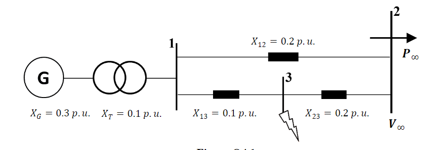
For the power system of Figure Q4.1, all per unit quantities have been calculated using a common base. The generator delivers power p∞ = 1 p. u. at a lagging power factor of cos= 0.93. i) Calculate the internal voltage of the generator, the maximum electrical power that the generator can deliver to the system during the steady state operation and the steady state rotor angle, σ0, of the generator. ii) A three-phase fault occurs at busbar 3 and it is cleared by simultaneously disconnecting lines 13 and 23. Following the fault clearing, the system continues to operate with only line 12 in service. Determine the new steady state rotor angle, σ1, of the generator and the maximum power the generator can deliver to the system post fault. iii) Assuming that the post fault condition is small disturbance stable and that there is no negative interaction among system controllers, calculate the critical clearing angle, σcr, at which the fault should be cleared to ensure the generator reaches a new steady state operating condition defined by σ1.


Load flow analysis
Load flow analysis is a study or numerical calculation of the power flow of power in steady-state conditions in any electrical system. It is used to determine the flow of power (real and reactive), voltage, or current in a system under any load conditions.
Nodal Matrix
The nodal matrix or simply known as admittance matrix, generally in engineering term it is called Y Matrix or Y bus, since it involve matrices so it is also referred as a n into n order matrix that represents a power system with n number of buses. It shows the buses' nodal admittance in a power system. The Y matrix is rather sparse in actual systems with thousands of buses. In the power system the transmission cables connect each bus to only a few other buses. Also the important data that one needs for have a power flow study is the Y Matrix.
Types of Buses
A bus is a type of system of communication that transfers data between the components inside a computer or between two or more computers. With multiple hardware connections, the earlier buses were parallel electrical wires but the term "bus" is now used for any type of physical arrangement which provides the same type of logical functions similar to the parallel electrical bus. Both parallel and bit connections are used by modern buses. They can be wired either electrical parallel or daisy chain topology or are connected by hubs which are switched same as in the case of Universal Serial Bus or USB.
For the power system of Figure Q4.1, all per unit quantities have been calculated using
a common base. The generator delivers power p∞ = 1 p. u. at a lagging power factor of
cos= 0.93.
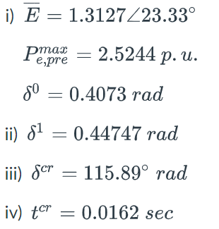
i) Calculate the internal voltage of the generator, the maximum electrical power
that the generator can deliver to the system during the steady state operation
and the steady state rotor angle, σ0, of the generator.
ii) A three-phase fault occurs at busbar 3 and it is cleared by simultaneously
disconnecting lines 13 and 23. Following the fault clearing, the system
continues to operate with only line 12 in service. Determine the new steady
state rotor angle, σ1, of the generator and the maximum power the generator
can deliver to the system post fault.
iii) Assuming that the post fault condition is small disturbance stable and that there
is no negative interaction among system controllers, calculate the critical
clearing angle, σcr, at which the fault should be cleared to ensure the generator
reaches a new steady state operating condition defined by σ1.
iv) If the rate of acceleration of the rotor during the fault is Cacc = 39 rad/sec^2
calculate the corresponding critical clearing time of the circuit breakers.

Step by step
Solved in 6 steps with 8 images


