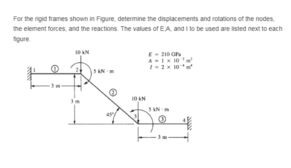
For the rigid frames shown in Figure, determine the displacements and rotations of the nodes, the element forces, and the reactions. The values of EA, and I to be used are listed next to each figure. 10 kN E = 210 GPa A = 1 × 10² m² I = 2 x 10⁴ m² 2₁ 5 kN - m 3 m 5 kN - m (3 3 m 3 m (2) 45% 10 kN
For the rigid frames shown in Figure, determine the displacements and rotations of the nodes, the element forces, and the reactions. The values of EA, and I to be used are listed next to each figure. 10 kN E = 210 GPa A = 1 × 10² m² I = 2 x 10⁴ m² 2₁ 5 kN - m 3 m 5 kN - m (3 3 m 3 m (2) 45% 10 kN

Mechanics of Materials (MindTap Course List)
9th Edition
ISBN:9781337093347
Author:Barry J. Goodno, James M. Gere
Publisher:Barry J. Goodno, James M. Gere
Chapter1: Tension, Compression, And Shear
Section: Chapter Questions
Problem 1.3.19P: A plane frame is restrained al joints A and C, as shown in the figure. Members AB and BC are pin...

Related questions

Question
Transcribed Image Text:For the rigid frames shown in Figure, determine the displacements and rotations of the nodes,
the element forces, and the reactions. The values of EA, and I to be used are listed next to each
figure.
10 kN
E = 210 GPa
A = 1 × 10² m²
I= 2 x 10⁴ m²
5 kN - m
5 kN - m
45°
3 m
O
3 m
10 kN
Expert Solution
This question has been solved!
Explore an expertly crafted, step-by-step solution for a thorough understanding of key concepts.

Step by step
Solved in 7 steps with 6 images

Knowledge Booster


Learn more about
Need a deep-dive on the concept behind this application? Look no further. Learn more about this topic, mechanical-engineering and related others by exploring similar questions and additional content below.Recommended textbooks for you
Mechanics of Materials (MindTap Course List)
Mechanical Engineering
ISBN:
9781337093347
Author:
Barry J. Goodno, James M. Gere
Publisher:
Cengage Learning
Mechanics of Materials (MindTap Course List)
Mechanical Engineering
ISBN:
9781337093347
Author:
Barry J. Goodno, James M. Gere
Publisher:
Cengage Learning