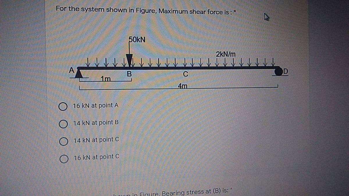
For the system shown in Figure, Maximum shear force is:* 50KN 2kN/m A C 1m 4m


Q: A rod of a variable cross-section shown in the following figure is subjected to two axial forces.…
A:
Q: The shaft of the gearbox, shown in the figure, rotates with an angular speed of w=73 rad/s and…
A: Key : Key is a temporary fastening which is inserted between shaft and its assembly (pulley, gear,…
Q: Determine the required shaft diameter using the maximum strain energy (Von Mises) hypothesis. Take…
A: Solution:- Given, Power P=19.2 KW Speed N=180 rpm L=0.8m, F=6…
Q: Consider the two-member frame shown in (Figure 1). Suppose that w1 = 250 N/m , w2 = 420 N/m . Follow…
A: Given data as per question
Q: a. A steel rod of 1 cm in diameter projects (4+R) cm from the wall as shown in figure 1. If the rod…
A: Givend=1cm=0.01mL=4+R∆L=0.222G=R+8.27×10¹⁰PaAskedF=?
Q: PROBLEM 1 Given is a thin-walled tube with the following data: Determine the following: a. Enclosed…
A:
Q: A cantilever with rectangular cross-section (width b and height h=2c) is subjected to a vertical…
A:
Q: Q2 A solid circular bar ABC consists of two segments, as shown in figure 2. One segment has diameter…
A: The diameter of the shaft can be determined by two criteria 1) Shear stress 2) Angle of twist Both…
Q: Figure 1: y P = 400 kN 30° 1000 mm A Area 30 mm 20 mm In Figure 1, the equilibrium shear force…
A: Given data :- force = 400KN find the shear force at point A.
Q: A certain circular shaft is subjected to a maximum equivalent bending moment of 36,000 in-lb and a…
A:
Q: The stepped shaft in the figure transmits 19.2 kW of power at 180 d/d (rpm). Determine the required…
A: P=19.2 KwN=180 rpmvon moses hypothesis L=0.8 mFind shaft =?τcm=72 mPaσcm=108 mPa
Q: A hollow aluminium shaft of 80 mm outer diameter & 60 mm inner diameter is rotating @ 5 Hz when…
A:
Q: a. A steel rod of 1 cm in diameter projects (4+R) cm from the wall as shown in figure 1. If the rod…
A: Write the given data: Understand the following figure for the given beam.
Q: (a) The tubular rotor shaft of a wind turbine shown in Figure 3(a) is of 50 mm and 40 mm outer and…
A: Given data Outer Diameter of Tubular shaft = Do = 50 mm = 0.05 mInner Diameter of Tubular Shaft = Di…
Q: A shaft rotating at 350 r.p.m. drives another shaft at 550 r.p.m. and transmits 10.5 kW hrough a…
A:
Q: The internal shear force at a certain section of a steel beam is V = 8.1 kN. The beam cross-section…
A:
Q: Q2c) The steel alloy shaft having a diameter of 38 mm is used to transmit torque, T as shown in…
A: Given: Solution:
Q: .A hollow steel shaft transmits 600 kW at 500 r.p.m. The maximum shear stress is 62.4 MPa. Find the…
A: We are authorized to answer one question at a time since you have not mentioned which question you…
Q: A thin wall spherical tank of diameter 1.5 m and wall thickness 65 mm has internal pressure of 20…
A:
Q: 1.69.Obtain the principal stresses and the related direction cosines for the following cases: 4 6. 4…
A: A)The Principal Stress; I1 = σx+σy+σz = 3 - 2 + 1 = 2 I2 = σxσy+σyσz+σzσx - τxy2 -τyz2-τzx2 =…
Q: Determine the maximum shear force in kN in the figure below. 30 kN 140 kN • m A D В C +2 m- 3 m 2 m→
A:
Q: The 16 x 22 x 25-mm rubber blocks shown in the figure are used in a double U shear mount to isolate…
A: Given data: ◆ Dimensions of rubber block: 16 mm × 22 mm × 25 mm ◆ Load applied: P = 300 N ◆ Downward…
Q: A solid circular steel shaft AB, held rigidly at both ends, has two different diameters as in…
A: Consider the Free Body Diagram: TA+TB=TCTA=ζJr =80*π32*20410TA=125663.706 N.mmTA=125.663 N.mTB=ζJr…
Q: 0.75 in 0.75 m The torque T = 300 KN.m. The tube thickness t = 10 mm and length L = 1.3 m. and G =…
A: Answer: (a) The average shear stress in the tube: 3.147 MPa. (b) The angle of twist: 1.3845E-4.
Q: HW8 A shaft rotating at 350 r.p.m. drives another shaft at 550 r.p.m. and transmits 10.5 kW through…
A: Given: N1=350 rpmN2=550 rpm Power transmit is 10.5 kW. Width of the belt is 80 mm. Thickness of the…
Q: A shaft supported on bearings 200mm apart transmits 187 kW at 200rpm. The maximum bending moment is…
A:
Q: The stepped shaft in the figure transmits 19.2 kW of power at 180 rpm. Maximum strain Determine the…
A: given data;power transmitted(P)=19.2KW =19.2*103w…
Q: 4) The thin walled cross-section, shown in figure, has an allowable shear stress of 2 ksi. Determine…
A:
Q: the nodal displacements are For the plane strain elements shown in the Figure given as (4, 4) uj =…
A: Solution: Given Data:
Q: if the cross-section shown in the figure has shear stress of 300psi at point P( located 0.25 in…
A:
Q: 2. A compound shaft consisting of an aluminum segment and steel segment is acted upon by two torques…
A:
Q: 4 m www.muthalinc.com R1 Figure P-68R=15 23. The shaft shown in Fig.3 is carries two pulleys each…
A: Data given-
Q: 40 N.m Da 0.5 m 280 N.m 150 N.m 2 0.3 m 0.4 m
A:
Q: 4. A hollow steel shaft undergoes a tensile axial load P and a moment M = 2 kN-m as seen below.…
A:
Q: 50 kN 250 mm 10 500 mm 1450 3 100 kNm 4 8. 7 6 The area of each boom is 150 mm2 and the thickness of…
A:
Q: Situation 1| Consider the figure 1 below. 3 - 25mmØ bolts are used to fasten a plate to a steel…
A:
Q: A ship's shaft operates at 150 rpm and resists a maximum shear stress of 50 MPa. The shaft has an…
A: To solve this problem, we have used torsion equation. Proper care of units must be taken.
Q: An 8.03-kg stone at the end of a steel (Young's modulus 2.0 x 10¹¹ N/m2) wire is being whirled in a…
A:
Q: Determine the maximum shear force in kN in the figure below. 2 kN/m B C A 4 m 2 m 5 kN
A:
Q: For the figure shown below. Find the maximum allowable value of P if the bending stresses are not…
A:
Q: The stepped shaft in the figure transmits 19.2 kW of power at 180 rpm. Maximum strain Determine the…
A:
Q: For the framc shown in the figure, Find the normal and shear stresses based on the following…
A: Given: The diameter of the pin at A, d = 10 mm The diameter of the pin at C, D = 15 mm
Q: A hydraulic punch press is used to punch a slot in a 0.30-in.-thick plate, as illustrated in the…
A: Given:Thickness of plate, t=0.3 inshear stress at plate, τ=36 ksid=1.25 ina=2.25 in
Q: A simply supported shaft arrangement is shown in the figure. A solid shaft of 50 mm diameter made of…
A:
Q: Two thin-walled aluminum tubes will be used to support a torque and they have same cross- section…
A: Introduction: When a shaft is torqued or twisted, shearing tension is created in the shaft. The…
Q: Figure P-68=15 R Q3. The shaft shown in Fig.3 is carries R1 R=15cm C. two pulleys each weighs 400 N.…
A: Data given- Weight of each pulley = 400 N Allowable shear stress = 56 MPa Allowable normal stress…
Q: The copper shaft (G= 44 GPa) is bonded to A the aluminum shaft (G= 26 GPa) at B point and their…
A: Given, Modulus of rigidity of copper,G=44GPaModulus of rigidity of aluminium,G=26GPaLength of AB,…
Q: A shaft composed of segments AC, CD, and DB is fastened to rigid supports and loaded as shown in the…
A:
Q: A belt drive consists of two V-belts in parallel, on grooved pulleys of the same size. The angle of…
A:

Step by step
Solved in 3 steps with 3 images


- A solid circular bar of steel (G = 78 GPa) transmits a torque T = 360 N - m. The allowable stresses in tension, compression, and shear arc 90 MPa, 70 MPa, and 40 MPa, respectively. Also, the allowable tensile strain is 220 x 10-6, Determine the minimum required diameter d of the bar, If the bar diameter d = 40 mm, what is Tmax?A W 360 x 79 steel beam is fixed at A. The beam has a length of 2.5 m and is subjected to a linearly varying distributed load with maximum intensity q0= 500 N/m on segment AB and a uniformly distributed load of intensity qQon segment EC. Calculate the state of plane stress at point D located 220 mm below the top of the beam and 0\3 m to the left of point B. Find the principal normal stresses and the maximum shear stress at D. Include the weight of the beam, See Table F-l(b), Appendix F, for beam properties.-11 A solid steel bar (G = 11.8 X 10⁶ psi ) of diameter d = 2,0 in. is subjected to torques T = 8.0 kip-in. acting in the directions shown in the figure. Determine the maximum shear, tensile, and compressive stresses in the bar and show these stresses on sketches of properly oriented stress elements. Determine the corresponding maximum strains (shear, tensile, and compressive) in the bar and show these strains on sketches of the deformed elements.
- A hollow circular tube having an inside diameter of 10.0 in, and a wall thickness of 1.0 in. (see figure) is subjected to a torque T = 1200 kip-in. Determine the maximum shear stress in the tube using (a) the approximate theory of thin-walled tubes, and (b) the exact torsion theory. Does the approximate theory give conservate or nonconservative results?• - 3 A rectangular plate in biaxial stress (see figure) is subjected to normal stresses u = 67 MPa (tension) and s = -23 MPa (compression). The plate has dimensions 400 X 550 X 20 mm and is made of steel with E = 200 GPa and v = 0.30. (a) Determine the maximum in-plane shear strain ?max in the plate. (b) Determine the change ?t in the thickness of the plate. (c) Determine the change ?t in the volume of the plate.The stepped shaft shown in the figure is required to transmit 600 kW of power at 400 rpm. The shaft has a full quarter-circular fillet, and the smaller diameter D1= 100 mm. If the allowable shear stress at the stress concentration is 100 MPa, at what diameter will this stress be reached? Is this diameter an upper or a lower limit on the value of D2?
- A thin-walled steel tube of rectangular cross section (see figure) has centerline dimensions b = 150 mm and h = 100 mm. The wall thickness t is constant and equal to 6.0 mm. Determine the shear stress in the tube due to a torque T = 1650 N · m. Determine the angle of twist (in degrees) if the length L of the tube is 1.2 m and the shear modulus G is 75 GPa.A pressurized cylindrical tank with flat ends is loaded by torques T and tensile forces P (sec figure), The tank has a radius of r = 125 mm and wall thickness t = 6.5 mm. The internal pressure p = 7.25 MPa and the torque T = 850 N m. (a) What is the maximum permissible value of the forces P if the allowable tensile stress in the wall of the cylinder is 160 MPa? (b) If forces P = 400 kN, what is the maximum acceptable internal pressure in the tank?A cylindrical pressure vessel having a radius r = 14 in. and wall thickness t = 0,5 in, is subjected to internal pressure p = 375 psi, In addition, a torque T = 90 kip-ft acts at each end of the cylinder (see figure), (a) Determine the maximum tensile stress ctniXand the maximum in-plane shear stress Tmjv in the wall of the cylinder. (b) If the allowable in-plane shear stress is 4.5 ksi, what is the maximum allowable torque T\ (c) If 7 = 150 kip-ft and allowable in-plane shear and allowable normal stresses are 4.5 ksi and 11.5 ksi, respectively, what is the minimum required wall thickness
- A punch for making a slotted hole in ID cards is shown in the figure part a. Assume that the hole produced by the punch can be described as a rectangle (12 mm X 3 mm) with two half circles (r = 1.5 mm) on the left and the right sides. If P = 10 N and the thickness of the ID card is 1 mm, what is the average shear stress in the card?The normal strain in the 45n direction on the surface of a circular tube (sec figure) is 880 × 10 when the torque T = 750 lb-in. The tube is made of copper alloy with G = 6.2 × 10⁶ psi and y = 0.35. If the outside diameter d2of the tube is 0.8 in., what is the inside diameter dt? If the allowable normal stress in the tube is 14 ksi, what is the maximum permissible inside diameter d?The flat bars shown in parts a and b of the figure are subjected to tensile forces P = 2.5 kN. Each bar has thickness t = 5.0 mm. (a) For the bar with a circular hole, determine the maximum stresses for hole diameters d = 12 mm and d = 20 mm il" the width h = 60 mm. (b) For the stepped bar with shoulder fillets, determine the maximum stresses Tor fillet radii R = 6 mm and R = 10 mm if the bar widths are h = 60 mm and c = 40 mm.