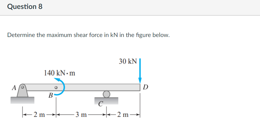
Determine the maximum shear force in kN in the figure below. 30 kN 140 kN • m A D В C +2 m- 3 m 2 m→


Q: A rod of a variable cross-section shown in the following figure is subjected to two axial forces.…
A:
Q: A material having a shear modulus G, is deformed under a pure shear stress as shown in the following…
A: Given, a= 2mm, b= 100 mm and G = 25 GPa
Q: Determine the required shaft diameter using the maximum strain energy (Von Mises) hypothesis. Take…
A: Solution:- Given, Power P=19.2 KW Speed N=180 rpm L=0.8m, F=6…
Q: A steel (E = 200 GPa) rod ABC is applied by the axial load as shown in Figure Q2(c). The diameter of…
A:
Q: A rigid beam is supported by a pin at A and two metallic wires at B and C. Determine the force P…
A:
Q: A bar with a right angle bend is supported by a collar A on smooth square rod, and by a roller at B.…
A:
Q: As shown in the figure below, determine the internal loadings at point C. В 0.1' m 0.5 m A -0.75 m…
A: Apply Equilibrium Conditions for fbd
Q: Consider a wooden block acted upon by force P = 5.00 kN. The value of the shear/tangential force…
A: Given data, P= 5 kN θ= 30° We need to find tangential force.
Q: Q2 A solid circular bar ABC consists of two segments, as shown in figure 2. One segment has diameter…
A: The diameter of the shaft can be determined by two criteria 1) Shear stress 2) Angle of twist Both…
Q: 2.1 A uniformly distributed load ofintensity g is applied through a circular area of radius a on the…
A:
Q: Figure 1: y P = 400 kN 30° 1000 mm A Area 30 mm 20 mm In Figure 1, the equilibrium shear force…
A: Given data :- force = 400KN find the shear force at point A.
Q: Q3: A shaft made of 40 C 8 steel is used to drive a machine. It rotates at 1500 r.p.m. The pulleys…
A: A torque, or moment of a force, is a measurement of a force's proclivity to cause a body to rotate.…
Q: Find shear stress at point B on the =cross section 10 AN 10 AN 2m 25 mm 10 m 5mm NA Given the…
A:
Q: As shown in the figure below, determine the internal loadings at point C. В 0.1 m 0.5 m A -0.75 m…
A:
Q: The stepped shaft in the figure transmits 19.2 kW of power at 180 d/d (rpm). Determine the required…
A: P=19.2 KwN=180 rpmvon moses hypothesis L=0.8 mFind shaft =?τcm=72 mPaσcm=108 mPa
Q: a. A steel rod of 1 cm in diameter projects (4+R) cm from the wall as shown in figure 1. If the rod…
A:
Q: A hollow aluminium shaft of 80 mm outer diameter & 60 mm inner diameter is rotating @ 5 Hz when…
A:
Q: 1 (c) Determine the maximum shear stress for the member shown in figure below. The lengths and…
A:
Q: A rigid beam is supported by a pin at A and two metallic wires at B and C. Determine the force P…
A:
Q: Strain-gages are attached to the element subject to plane deformation, as shown in the figure, and…
A:
Q: A steel (E = 200 GPa) rod ABC is applied by the axial load as shown in Figure Q2(c). The diameter of…
A:
Q: A thin walled tube of circular cross section with mean radius r has a central web which divides into…
A:
Q: A material having a shear modulus G, is deformed under a pure shear stress as shown in the following…
A:
Q: A shaft rotating at 350 r.p.m. drives another shaft at 550 r.p.m. and transmits 10.5 kW hrough a…
A:
Q: Determine the effective length factor (K) for all columns in the figure below: C W16 X 57 W16 X 57 I…
A: ACCORDING TO DATABOOK, MACHINE DESIGN DATA BOOK BY V.B. BHANDARI, PAGE NO. 256, TABLE NAME: TABLE…
Q: P1. A uniformly tapering circular rod is subjected to load as shown in the figure . Determine the…
A: When an axial load is applied to a bar it tends to get deformed. This elongation depends upon the…
Q: A rigid beam is supported by a pin at A and two metallic wires at B and C. Determine the force P…
A:
Q: Bar (1) has a length of L1 = 2.4 m, and bar (2) has a length of L2 = 0.63 m. Initially, there is a…
A:
Q: À rectangular steel plate (thickness 4mm) is subjected to a uniform biaxial stress field as shown in…
A:
Q: H.W.8 When an axial load is applied to the ends of the two- segment rod shown in Figure P2.1, the…
A: Given:- ε2=2075 μm/m a=1.2m b=2.8m To find:- (a) Elongation of segment(2) (b) Strain in segment (1)
Q: Draw the free body diagrams for each part in the figures below: P 4P 4P 2P 0.5m 0.5 m m' 1.5 m 1.5 m…
A: Answer is given below
Q: Determine the maximum shear force in kN in the figure below. 2 kN/m B A C 5 kN 4 m 2 m O -10 O 10 O…
A:
Q: The Force shown in the figure is F = 30i +40 j–120k N F D 4 m
A: Given F=30i×40j-120-k N
Q: H.W.10 Rigid bar ABCD is supported by two bars as shown in Figure P2.7. There is no strain in the…
A: It is given that the Bar is rigid, thus the bar before and after loading will remain straight. To…
Q: A centered force P and a horizontal force Qx are applied at point C of the rectangular bar shown in…
A: Given that, The strain rosette has following data,ε1=-60×10-6ε2=240×10-6ε3=200×10-6Modulus of…
Q: For the system shown in Figure, Maximum shear force is:* 50KN 2kN/m A C 1m 4m
A:
Q: Determine the maximum shear force in kN in the figure below. 10 kN/m 25 kN • m A E B |C D 1 m 1m 3 m…
A: Answer: The maximum shear force is +/- 20 kN.
Q: Consider the object shown in (Figure 1). Suppose that w1 = 2.1 kN/m , w2 = 1.3 kN/m . Determine the…
A: Given data as per question w1 = 2.1 kN/m w2 = 1.3 kN/m.
Q: C The rectangular bar has a width w = 100 mm and a thickness of 75 mm. The shear stress in the plane…
A:
Q: and a gauge length of 50 mm is given in the figure. Deter a) the modulus of elasticity b) the yield…
A:
Q: F2 (2 Q1) Axial displacement of point C in the system shown on the left is 0.01 cm. Find the maximum…
A: Write the given value using suitable variables. Here ΔlC signifies point C axial displacement, F2…
Q: Determine the maximum shear force in kN in the figure below. 2 kN/m B C A 4 m 2 m 5 kN
A:
Q: A bar (AC) is effected by a torque (T) at the free end by (2T) in the opposite direction at the…
A:
Q: P2.12 (WP A thin triangular plate PQR forms a right angle at point Q. During deformation, point Q…
A:
Q: The copper shaft (G= 44 GPa) is bonded to A the aluminum shaft (G= 26 GPa) at B point and their…
A: Given, Modulus of rigidity of copper,G=44GPaModulus of rigidity of aluminium,G=26GPaLength of AB,…
Q: Ropes J, K, and L with their ends attached to each other as shown supports a downward force Q=100N.…
A:
Q: An initially rectangular element of a material is deformed into the shape shown in the figure.…
A: Ratio of change in length to original length is known as normal strain. Angular deformation of…
Q: F2. F3 F1 L2 A pipe is subjected to loads as shown in figure. The outer and inner diameters of the…
A: Given: The inner diameter of pipe, d = 79 mm The outer diameter of pipe, D = 99.2 mm The force along…
Q: (2) The strength condition of composition of bending and torsion is _M₂_ √ M² + (aT)² ≤ [0_16] J.= W…
A:
Q: The maximum principle stress for the stress state shown in the figure is (b) 20 (a) o (c) 30 (d) 1.5…
A: From the data given in question, Normal stress along x direction = σx = σ Normal stress along y…

Step by step
Solved in 3 steps with 3 images


- The shear stresses t in a rectangular beam arc given by Eq. (5-43): in which Fis the shear force, / is the moment of inertia of the cross-sectional area, /lis the height of the beam, and i] is the distance from the neutral axis to the point where the shear stress is being determined (Fig. 5-32). By integrating over the cross-sectional area, show that the resultant of the shear stresses is equal to the shear force V.A circular aluminum tube subjected to pure torsion by torques T(sec figure) has an outer radius r2equal to 1.5 times the inner radius r1. (a) If the maximum shear strain in the tube is measured as 400 × 10-6 rad, what is the shear strain y1at the inner surface? (b) If the maximum a1lo-abk rate of twist is 0.125 °/m and the maximum shear strain is to be kept at 400 × 10-6 rad by adjusting the torque T, that is the minimum required outer radius ( r2)Min?A thin-walled rectangular tube has uniform thickness t and dimensions a x b to the median line of the cross section (see figure). How does the shear stress in the tube vary with the ratio = a/b if the total length Lmof the median line of the cross section and the torque T remain constant? From your results, show that the shear stress is smallest when the tube is square (ß = 1).
- A flexible connection consisting of rubber pads (thickness f = 9 mm) bonded to steel plates is shown in the figure. The pads are 160 mm long and SO mm wide. (a) Find the average shear strain yaiTi in the rubber if the force P = 16 kN and the shear modulus for the rubber is G = 1250 kPa. (b) Find the relative horizontal displacement 3 between the interior plate and the outer plates.A thin-walled aluminum tube of rectangular cross section (sec fig me) has a centerline dimensions b = 6.0 in. and b = 4.0 in. The wall thickness t is constant and equal to 0.25 in. Determine the shear stress in the tube due to a torque T = 15 kip-in. Determine the angle of twist (in degrees) if the length L of the tube is 50 in. and the shear modulus G is 4.0 x 10⁶ psi.A tie-down on the deck of a sailboat consists of a bent bar boiled at both ends, as shown in the figure. The diameter dBof the bar is 1/4 in., the diameter D Wof the washers is 7/8 in., and the thickness is of the fiberglass deck is 3/8 in. If the allowable shear stress in the fiberglass is 300 psi, and the allowable bearing pressure between the washer and the fiberglass is 550 psi, what is the allowable load P allowon the tie-down?
- A punch for making a slotted hole in ID cards is shown in the figure part a. Assume that the hole produced by the punch can be described as a rectangle (12 mm X 3 mm) with two half circles (r = 1.5 mm) on the left and the right sides. If P = 10 N and the thickness of the ID card is 1 mm, what is the average shear stress in the card?A hollow steel box beam has the rectangular cross section shown in the figure. Determine the maximum allowable shear force K that may act on the beam if the allowable shear stress is 36 MPa. cA vertical pole consisting of a circular tube of outer diameter 5 in. and inner diameter 4.5 in. is loaded by a linearly varying distributed force with maximum intensity of q0, Find the maximum shear stress in the pole.
- .4 The stresses on an clement arc known to be sx= 120 MPa, sy= 100 MPa, and txy= 75 MPa. Find the stresses on an inclined section through the element at an angle ? = 45°.Solve the preceding problem if the norm al and shear stresses acting on the element are sx = 2100 kPa, sy= 300 kPa, and txy= -560 kPa, and the seam is oriented at an angle of 22.5° to the clement.Solve the preceding problem if the normal and shear stresses acting on element B are 56 MPa, 17 MPa, and 27 MPa (in the directions shown in the figure) and the angle is 40° (clockwise).