For the two gears, A and B, in Figure 3-23, compute the relative deflection in shaft 2 due to the forces shown in Figure 3-23 (c). These separating forces, or normal forces, are discussed in Chapters 9 and 10. It is customary to consider the loads at the gears and the reactions at the bearings
For the two gears, A and B, in Figure 3-23, compute the relative deflection in shaft 2 due to the forces shown in Figure 3-23 (c). These separating forces, or normal forces, are discussed in Chapters 9 and 10. It is customary to consider the loads at the gears and the reactions at the bearings

Power System Analysis and Design (MindTap Course List)
6th Edition
ISBN:9781305632134
Author:J. Duncan Glover, Thomas Overbye, Mulukutla S. Sarma
Publisher:J. Duncan Glover, Thomas Overbye, Mulukutla S. Sarma
Chapter6: Power Flows
Section: Chapter Questions
Problem 6.53P

Related questions

Question
For the two gears, A and B, in Figure 3-23, compute the relative deflection in shaft 2 due to the forces shown in Figure 3-23 (c). These separating forces, or normal forces, are discussed in Chapters 9 and 10.
It is customary to consider the loads at the gears and the reactions at the bearings
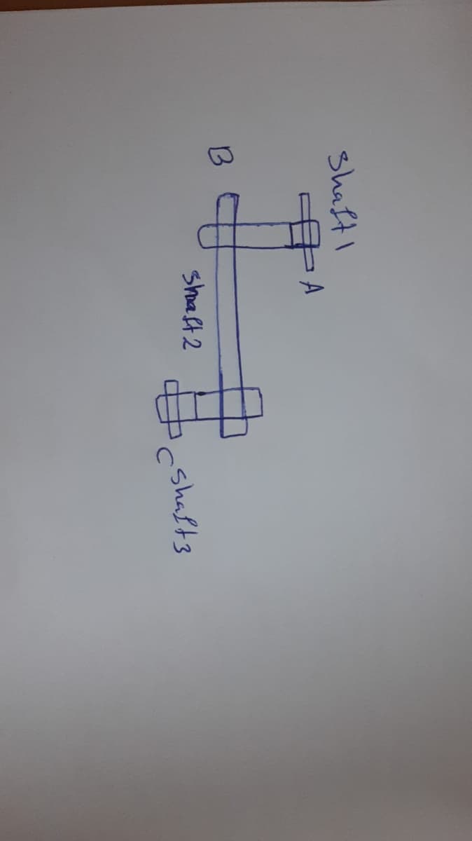
Transcribed Image Text:Shaft!
B
A
$₁
shaft 2
shafts
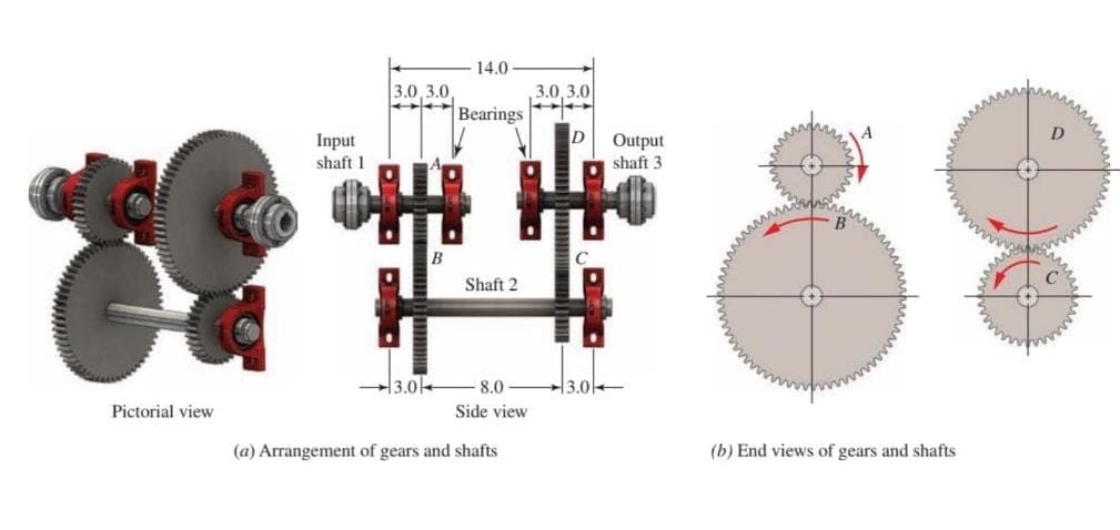
Transcribed Image Text:Pictorial view
Input
shaft 1
3.0,3.0,
TA Bearings
3.0
14.0
B
Shaft 2
D
Output
shaft 3
HK
-8.0
Side view
(a) Arrangement of gears and shafts
3.0,3.0
3.0-
(b) End views of gears and shafts
Expert Solution
This question has been solved!
Explore an expertly crafted, step-by-step solution for a thorough understanding of key concepts.

Step by step
Solved in 4 steps with 6 images

Knowledge Booster


Learn more about
Need a deep-dive on the concept behind this application? Look no further. Learn more about this topic, electrical-engineering and related others by exploring similar questions and additional content below.Recommended textbooks for you
Power System Analysis and Design (MindTap Course …
Electrical Engineering
ISBN:
9781305632134
Author:
J. Duncan Glover, Thomas Overbye, Mulukutla S. Sarma
Publisher:
Cengage Learning
Power System Analysis and Design (MindTap Course …
Electrical Engineering
ISBN:
9781305632134
Author:
J. Duncan Glover, Thomas Overbye, Mulukutla S. Sarma
Publisher:
Cengage Learning