Design a basic wide-band, RC band stop filter with a lower cut-off frequency of 200HZ and a higher cut-off frequency of 1000Hz. Var V Band Stop Response -3d8 Pass Band Pass Band Frequency (z) -3d8 Low Pass Response High Pass Response Frequency (Hz) Figure 1: Band Stop Filter Characteristics Assuming a capacitor, C value for both filter sections (CLP, CHP) of 0.2uF, calculate the values of the two resistors, RLP and RHP using the formula: 1. From the Low pass filter formula, Find RLP: fi 2nRLpCLP 2. From the High pass filter formula, Find RHP: 1 2nRHp CHP 3. Calculate the center frequency (f) and Bandwidth (BW): a. fc = Vfi x fa
Design a basic wide-band, RC band stop filter with a lower cut-off frequency of 200HZ and a higher cut-off frequency of 1000Hz. Var V Band Stop Response -3d8 Pass Band Pass Band Frequency (z) -3d8 Low Pass Response High Pass Response Frequency (Hz) Figure 1: Band Stop Filter Characteristics Assuming a capacitor, C value for both filter sections (CLP, CHP) of 0.2uF, calculate the values of the two resistors, RLP and RHP using the formula: 1. From the Low pass filter formula, Find RLP: fi 2nRLpCLP 2. From the High pass filter formula, Find RHP: 1 2nRHp CHP 3. Calculate the center frequency (f) and Bandwidth (BW): a. fc = Vfi x fa

Introductory Circuit Analysis (13th Edition)
13th Edition
ISBN:9780133923605
Author:Robert L. Boylestad
Publisher:Robert L. Boylestad
Chapter1: Introduction
Section: Chapter Questions
Problem 1P: Visit your local library (at school or home) and describe the extent to which it provides literature...

Related questions
Question
solve the second image
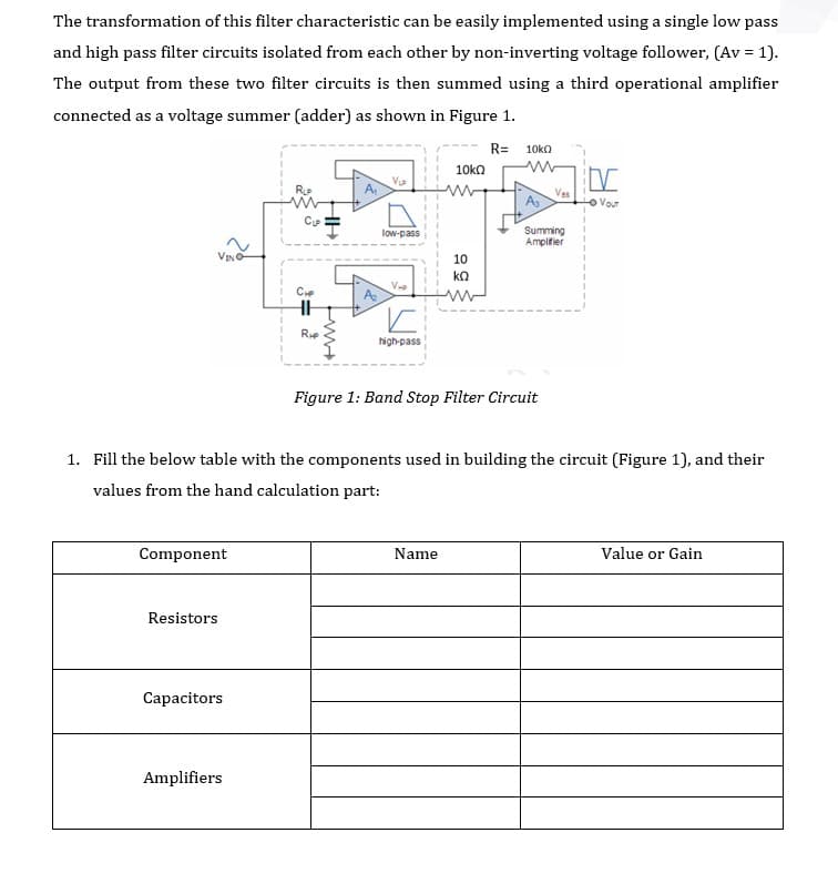
Transcribed Image Text:The transformation of this filter characteristic can be easily implemented using a single low pass
and high pass filter circuits isolated from each other by non-inverting voltage follower, (Av = 1).
The output from these two filter circuits is then summed using a third operational amplifier
connected as a voltage summer (adder) as shown in Figure 1.
R=
10ka
10ka
V
A,
Ves
As
OVour
Summing
Amplifier
low-pass
VINO
10
ko
V
A
Ce
Rie
high-pass
Figure 1: Band Stop Filter Circuit
1. Fill the below table with the components used in building the circuit (Figure 1), and their
values from the hand calculation part:
Component
Name
Value or Gain
Resistors
Capacitors
Amplifiers
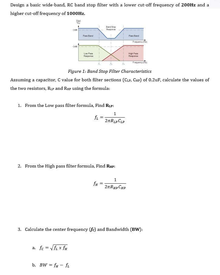
Transcribed Image Text:Design a basic wide-band, RC band stop filter with a lower cut-off frequency of 200HZ and a
higher cut-off frequency of 1000Hz.
Var
V
Band Stop
Response
-3 d8
Pass Band
Pass Band
Frequency (ftz)
-3d8
Low Pass
Response
High Pass
Response
Frequency (z)
Figure 1: Band Stop Filter Characteristics
Assuming a capacitor, C value for both filter sections (CLP, CHP) of 0.2uF, calculate the values of
the two resistors, RLP and RHP using the formula:
1. From the Low pass filter formula, Find RLP:
fi
2nRLpCLP
2. From the High pass filter formula, Find RHP:
1
2nRHp CHP
3. Calculate the center frequency (f) and Bandwidth (BW):
a. fc = Vfi x fu
b. BW = f# - f.
Expert Solution
This question has been solved!
Explore an expertly crafted, step-by-step solution for a thorough understanding of key concepts.

Step by step
Solved in 4 steps with 4 images

Knowledge Booster


Learn more about
Need a deep-dive on the concept behind this application? Look no further. Learn more about this topic, electrical-engineering and related others by exploring similar questions and additional content below.Recommended textbooks for you
Introductory Circuit Analysis (13th Edition)
Electrical Engineering
ISBN:
9780133923605
Author:
Robert L. Boylestad
Publisher:
PEARSON

Delmar's Standard Textbook Of Electricity
Electrical Engineering
ISBN:
9781337900348
Author:
Stephen L. Herman
Publisher:
Cengage Learning

Programmable Logic Controllers
Electrical Engineering
ISBN:
9780073373843
Author:
Frank D. Petruzella
Publisher:
McGraw-Hill Education
Introductory Circuit Analysis (13th Edition)
Electrical Engineering
ISBN:
9780133923605
Author:
Robert L. Boylestad
Publisher:
PEARSON
Delmar's Standard Textbook Of Electricity
Electrical Engineering
ISBN:
9781337900348
Author:
Stephen L. Herman
Publisher:
Cengage Learning
Programmable Logic Controllers
Electrical Engineering
ISBN:
9780073373843
Author:
Frank D. Petruzella
Publisher:
McGraw-Hill Education

Fundamentals of Electric Circuits
Electrical Engineering
ISBN:
9780078028229
Author:
Charles K Alexander, Matthew Sadiku
Publisher:
McGraw-Hill Education

Electric Circuits. (11th Edition)
Electrical Engineering
ISBN:
9780134746968
Author:
James W. Nilsson, Susan Riedel
Publisher:
PEARSON

Engineering Electromagnetics
Electrical Engineering
ISBN:
9780078028151
Author:
Hayt, William H. (william Hart), Jr, BUCK, John A.
Publisher:
Mcgraw-hill Education,