Given is the parallel connected RLC network as depicted in the figure below. L R 1)I(t) iz(1) The controllable current source I(t) is the system input. The current ig(t) flowing through a resistive load is the system output. The constant system parameters ar the resistance R, the capacitance C, and the inductance L. a) Using the Kirchhoff's current and voltage laws, derive and write down the linear differential equation which describes the input-output behavior of the RLC network. Based on that, derive the input-output transfer function. Calculate the poles and zeros of the system. Determine the parametric condition (i.e. relationship between R, L, and C values) for which the system has only the real poles and is, thus, not oscillatory. For the following, the parameter values R=10, L=0.01, C=0.1 are assumed. b) For the above RLC network, assume a closed-loop system with the feedback gain K. Calculate the optimal value of the K-gain so that the closed-loop system has the maximal possible natural frequency (i.e. max ) and is critically damped (i.e. =1) at the same time.
Given is the parallel connected RLC network as depicted in the figure below. L R 1)I(t) iz(1) The controllable current source I(t) is the system input. The current ig(t) flowing through a resistive load is the system output. The constant system parameters ar the resistance R, the capacitance C, and the inductance L. a) Using the Kirchhoff's current and voltage laws, derive and write down the linear differential equation which describes the input-output behavior of the RLC network. Based on that, derive the input-output transfer function. Calculate the poles and zeros of the system. Determine the parametric condition (i.e. relationship between R, L, and C values) for which the system has only the real poles and is, thus, not oscillatory. For the following, the parameter values R=10, L=0.01, C=0.1 are assumed. b) For the above RLC network, assume a closed-loop system with the feedback gain K. Calculate the optimal value of the K-gain so that the closed-loop system has the maximal possible natural frequency (i.e. max ) and is critically damped (i.e. =1) at the same time.

Introductory Circuit Analysis (13th Edition)
13th Edition
ISBN:9780133923605
Author:Robert L. Boylestad
Publisher:Robert L. Boylestad
Chapter1: Introduction
Section: Chapter Questions
Problem 1P: Visit your local library (at school or home) and describe the extent to which it provides literature...

Related questions
Question
100%
Can u help with these questions? Matlab is not needed for those.
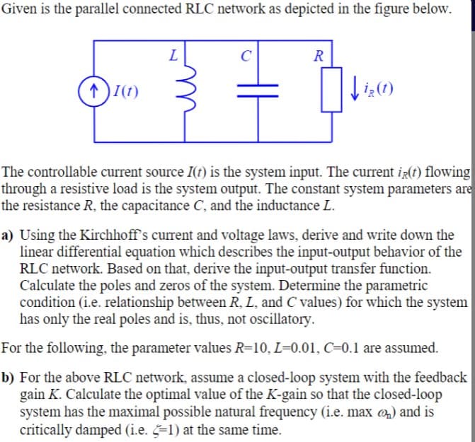
Transcribed Image Text:Given is the parallel connected RLC network as depicted in the figure below.
L
C
R
(↑)I(1)
↑ )I(1)
The controllable current source I(t) is the system input. The current ig(t) flowing
through a resistive load is the system output. The constant system parameters are
the resistance R, the capacitance C, and the inductance L.
a) Using the Kirchhoff's current and voltage laws, derive and write down the
linear differential equation which describes the input-output behavior of the
RLC network. Based on that, derive the input-output transfer function.
Calculate the poles and zeros of the system. Determine the parametric
condition (i.e. relationship between R, L, and C values) for which the system
has only the real poles and is, thus, not oscillatory.
For the following, the parameter values R=10, L=0.01, C=0.1 are assumed.
b) For the above RLC network, assume a closed-loop system with the feedback
gain K. Calculate the optimal value of the K-gain so that the closed-loop
system has the maximal possible natural frequency (i.e. max @n) and is
critically damped (i.e. =1) at the same time.
Expert Solution
This question has been solved!
Explore an expertly crafted, step-by-step solution for a thorough understanding of key concepts.

Step by step
Solved in 8 steps with 4 images

Knowledge Booster


Learn more about
Need a deep-dive on the concept behind this application? Look no further. Learn more about this topic, electrical-engineering and related others by exploring similar questions and additional content below.Recommended textbooks for you
Introductory Circuit Analysis (13th Edition)
Electrical Engineering
ISBN:
9780133923605
Author:
Robert L. Boylestad
Publisher:
PEARSON

Delmar's Standard Textbook Of Electricity
Electrical Engineering
ISBN:
9781337900348
Author:
Stephen L. Herman
Publisher:
Cengage Learning

Programmable Logic Controllers
Electrical Engineering
ISBN:
9780073373843
Author:
Frank D. Petruzella
Publisher:
McGraw-Hill Education
Introductory Circuit Analysis (13th Edition)
Electrical Engineering
ISBN:
9780133923605
Author:
Robert L. Boylestad
Publisher:
PEARSON
Delmar's Standard Textbook Of Electricity
Electrical Engineering
ISBN:
9781337900348
Author:
Stephen L. Herman
Publisher:
Cengage Learning
Programmable Logic Controllers
Electrical Engineering
ISBN:
9780073373843
Author:
Frank D. Petruzella
Publisher:
McGraw-Hill Education

Fundamentals of Electric Circuits
Electrical Engineering
ISBN:
9780078028229
Author:
Charles K Alexander, Matthew Sadiku
Publisher:
McGraw-Hill Education

Electric Circuits. (11th Edition)
Electrical Engineering
ISBN:
9780134746968
Author:
James W. Nilsson, Susan Riedel
Publisher:
PEARSON

Engineering Electromagnetics
Electrical Engineering
ISBN:
9780078028151
Author:
Hayt, William H. (william Hart), Jr, BUCK, John A.
Publisher:
Mcgraw-hill Education,