Given R1=1k and R2=10k, what is C so that |Vout/Vin|=0.1 when the frequency of Vin is 3322 Hz? R2 Vin R, Vout


Q: 1) Setup the circuits in Figure 10.1. Plot the magnitude and the phase of the frequency response…
A: An OPAMP(operational amplifier) is an integrated electronic circuit that is used to amplify weak…
Q: The bandwidth is the frequency band between half-power frequencies: B = W₂ W1
A: why the bandwidth is the frequency band between half power frequencis: B=w2-w1 So we have to Prove…
Q: Calculate the strength of a signal in dBm0 if it has an absolute power level of -27dBm at -24 dBm…
A: TLP stands for Transmission Level Point. Zero Transmission Level Point or power at 0 TLP is denoted…
Q: Low Frequency Response: Compute for the following. a. re 9V 2.3 ΚΩ 30 ΚΩ 1uF 1.6 ΚΩ 1uF 11 1uF Η 5.6…
A: Given:
Q: tov fle tollowing circuit , the in-Voltage is 100V per o Eo 1mH Find: A The max voltage (Justify) B…
A:
Q: R Vout Vin 1. Find the cut off frequency of the circuit given in Figure 1 with L=0.625 mH, R-10 2…
A: The inductive reactance of an inductor is XL=2*π*f*L=2*3.14*f*0.625*10-3=3.925*10-3f Ω The output…
Q: Determine the Nyquist rate in (Hz) for the following signal: g(t) = 3 cos2 (148t). Select one: O a.…
A: Given data, Signal is gt=3cos2148t
Q: 83. An impedance Z, is in series to the two impedances Z₁ = 20-j100 and Z₂ = 10-1200 that are…
A: Since you have asked multiple questions, we will solve the first question for you. If you want any…
Q: The frequency response H(w) for the system y(n)=x(n-1)-x(n+2) 2sin(1.5w)e^(-j0.5w+jr/2) O…
A: Given, The difference equation of the system is , y(n) = x(n-1) - x(n+2)
Q: Q2. For the system shown in figure beside; Given that: gı(t) 91(t) = 10* II (10-) G2(f) = 1 x(t)…
A: Given : g1 (t) = 104 π(t/10 -4) from the Figure identify given values we,get G1(f) = 104 x 10-4…
Q: Q2. Find the indicated quantities for the circuit of Figure (2) . a. Resonant frequency expressed as…
A: “Since you have posted a question with multiple sub-parts, we will solve the first three subparts…
Q: Q1) Draw the medulation cnd den tann block dragrams of Amplitude Medulation - Vesti gial side band…
A: Modulation and demodulation block diagrams of Amplitude Modulation - Vestigial Sideband(AM-VSB):-
Q: are two loops in a.. signal-flow graph that do not * .have a common node nontouching loops three…
A: Non touching loops are those loops which not sharing any node
Q: Given: hie = 1 kN and hre =75. Find the cutoff frequency due to C2 = 10 µF Vee - 24vd 1SOK 10K 22K…
A: Given data, hie=1 kΩhfe=75C2=10μF
Q: For the opamp circuit shown below figure, calculate the followings by assuming Ap=0o, Please mark…
A:
Q: Vout Vin 1. Find the cut off frequency of the circuit given in Figure 1 with L=0.625 mH, R-10 2 and…
A: The given circuit is shown below,
Q: The frequency response of a control system is given in the following table: Frequency (radisec) Gain…
A: Given frequency response of control system is -
Q: Consider the given circuit shown below and find its cutoff frequency (in KHz) 22k 22k V₁-WWW 330pF…
A: Given circuit, R1=R2=22 kΩC1=C2=330 pF
Q: P 0.8 pf lagging + Vo P 0.9 pf lagging
A: Given data, is=9+j0 A, P1=50 W, P2=56 W Circuit diagram is given as,
Q: three impedance Za, Zb and ZC are connected in parallel. If at 60 Hz, Za=0+j8; Zb=0-j2 and Zc=5+j0…
A: Za=0+j8; Zb=0-j2 and Zc=5+j0 ohms, f=60Hz
Q: Calculate the resonant frequency of the network show below. imm www R2 Az 2 46
A:
Q: A 16-PSK system with a carrier power of - 125 dB, a noise power of 1x 10^-15 W and operating…
A: According to the question,
Q: Answer the following Draw, Illustrate and label your schematic diagram before solving the problem.…
A:
Q: 12-2 (a) Determine the ms nolse vollage produced by a 120-kS2 resistance in an 80-KHz bandwidih al…
A: The solution is given below
Q: H.W: A resistor of resistance R=1000 N is maintained at 17 °C and it shunted by 100 µH inductor.…
A: The resistance of the resistor is 1000 Ω The temperature is 170C 17+273=290 K The Boltzman…
Q: Q2. For the system shown in figure beside; Given that: g:(t) 91(t) = 10 * I () G2) = 1 x(t) y(t)…
A:
Q: 2. A series circuit with R = 150 and L= 0.6 H and C = 42 µF, calcu the resonant lower, and upper…
A: In this question we will find resonant frequency and half power frequencies of series RLC circuit ..
Q: Q4/ Determine and sketch the magnitude and phase of H(w) for the following system y(n)=x(n-1)-x(n-2)…
A:
Q: 3. Prove that block diagram shown below can produce AM signal. A cos w t m square Divide the…
A: Let signal is xt then xt is given as-xt=Amcosωmt.Accosωct2+Accosωct2xt=Am2 Ac2…
Q: What is the frequency rang of C-band? * O 8.5 to 12.5 GHz O 3.4 to 6.425 GHz O 12.95 to 14.95 GHz O…
A: C band is one of the frequency bands in the microwave spectrum. It's range is approximately from…
Q: Low Frequency Response: Compute for the following. e. Fcl(output) 9V 2.3 ΚΩ 330 ΚΩ 1uF HH 1.6 ΚΩ 1uF…
A: BJT: It is three terminal semiconductor device that is used as a switch and amplifying the gain of…
Q: a. 3. We can find the frequency where the GAIN is 0 dB and the phase (phi) at that frequency. Then,…
A: We are authorized to answer only 1 question a time since you have not mentioned which question you…
Q: How many decades does the frequency span of 30 Hz to 15 000 Hz represents? (desades) What upper…
A: One decade contains 10 Hz Frequency Means 0 to 10 hz band means 1 decade Another 10 hz to 100 hz…
Q: lc = 14mA. Determine the lower cutoff frequency f (in kHz) ? Vee 250 R 200 Vee MF 100 PF Asoume
A: The given circuit diagram is shown below, From the above figure,RE=R2=200ΩRS=250ΩC=12πμFand IC=14…
Q: 1. Find the cut off frequency of the circuit given in Figure 1 with L=0.625 mH, R=10 N and amplitude…
A: The given RL circuit is
Q: Vc 10uF i C1 V1 V2 R1 Kr 27 MM L1 fo 10 KHz Zeq +
A: For this problem we can easily calculate magnitudes of voltages by finding node voltage V2
Q: Closed loop poles in a second order system -8 + 6j and -8-6j then what is the natural frequency of…
A:
Q: The attenuation of a signal is -10 dB. What is the final signal power if it was originally 5 W?
A: Attenuation means degradation of output power with respect to the input power because of some losses…
Q: Determine the resonant frequency. * +Vcc R1 HtoVout C4 C2 200 pF HE L2 000, 50 mH 10 mH None of the…
A: Determine the resonant frequency for the given Hartley Oscillator ?
Q: PART B ou he RL loaded band filter supressor circwif shawn belbw- If the charge is 20Ke , the…
A: Hi answer for all part is given below Please find the attachments below.
Q: R1 C2 Vout -Vin R2 a) For o→0, what is the current I(1) through R1? b) For o→ o, what is the current…
A:
Q: Problem (2) The Figure shows a Wien-bridge network. What is the frequency at which the phase shift…
A: Frequency at which the phase shift between input and output is zero,f=12πR1C1R2C2Here,f=12πRCRC…
Q: 3. Prove that block diagram shown below can produce AM signal. A cos wt square Divide the frequency…
A: Aim- We need to proove the following diagram can produce AM signal
Q: Figure Q2(e) shows two 3rd-order Butterworth low-pass filter. Do these twofilters have the same…
A: When a second-order low-pass filter is cascaded to a first-order low pass filter, then the modified…
Q: Compute the cutoff frequency. C C 4.7 nF 4.7 nF 44 O2 kHz O 1.4 kHz O2.82 kHz 03.12 kHz R₂ 12 kQ www…
A:
Q: SOLUE: Rrom tu- InTAL :? Iz? Vz.? Ry=2 Rz = 21
A: Use basic network series and parallel circuit reduction techniques Here the network has series…
Q: Q1) For the network of Figure below, where r=6.932 a. Find Avmid = Vol Vi. b. Calculate Zi. c.…
A:
Q: A resistor of resistance R=1000 2 is maintained at 17 °C and it shunted by 100 uH inductor.…
A: Given R=1000 ohms L=100uH T=17°C
Q: 3. Prove that block diagram shown below can produce AM signal. A, cos wt square Divide the frequency…
A:
Q: 1. Find the cut off frequency of the circuit given in Figure 1 with R=10 2, C=4.7 uF and amplitude…
A:
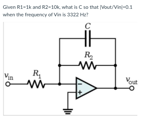
This is Inverted Op amplifier ,
Resistance R1=1K, R2= 10K then value of capacitance C if frequency f= 3322Hz.

Trending now
This is a popular solution!

Step by step
Solved in 2 steps with 1 images


- A) what is the relationship between frequency and eavelenght? ( direct or inverse) B) what is the relationship between period and frequency? ( direct or inverse)In the following figure, R=9kΩ ad Cf=3nF. Vin(t)=5sin(2pi*10khz*t) draw the output waveform Vin and Vo and derive the expression of the Vo(t) as a function of time & Vo(f) as a function of varying signal frequency.Answer the following Draw, Illustrate and label your schematic diagram before solving the problem. 2.) If C1 = C2 = 70 nF, determine the output frequencies produced by this arrangement: a) when R1 = R2 = 1.2k ohms and b) when R1 = R2 = 4k ohms These might help as a guide to answer the question..
- Q12.52 a,b,c from Q12.40Answer the following with illustration and solutions. 2.) If C1 = C2 = 100pF, determine the output frequencies produced by this arrangement:a. (a) when R1 = R2 = 12kilo-ohms andb. (b) when R1 = R2 = 8kilo-ohms See the example below..A Parallel Resonant ckt is given in the figure. Calculate Wo, W1, W2 , QF & Bw.
- Av =2; Rin = 100KΩ; Assume β=100, and bias for maximum swing. Select any frequency from 95-102MHz i.e 100MHz and calculate the value of missing components R1,,R2.Draft the magnitude of the total (not real) Impedance Z into the diagram ( |Z| in Ω - y-axis and f in Hz - x-axis ) . You do not need to derive an analytical expression, but you can. Please add relevant parameters such as interesting frequencies and limits to the draft.why the frequency fT is called the ? unity gain frequency
- Determine the gain margin and phase margin for a system that gave the following open-loop experimental frequency response data: a. At frequency=0.004 Hz; a gain of 1.00 and phase -120 degrees, b. At frequency=0.020 Hz; a gain of 0.45 and phase of 180 degreesDetermine: a. VGSQ and IDQ.b. VDS,VD,VG,andVS.For The Table 1-Find the cutoff frequency by changing the frequency until Vo becomes 0.707Vi. 2-Graph the gain and the phase against frequency.