Given the circuit fed by 50HZ voltage source Vs, knowing that Z1 is an inductive load with 0.8 power factor and Ż2 is a capacitive load with 0.6 power factor, please answer the following questions with detailed steps a) Find the power factor of the parallel of Z1 and Z2. b) Find the phasor Is. ( given V1 = 200<0 Volts) c) Find the lost power in the line. d) Find the voltage of the source Vs. e) Find the value of the capacitor to be added parallel to the loads to have a unity power factor
Given the circuit fed by 50HZ voltage source Vs, knowing that Z1 is an inductive load with 0.8 power factor and Ż2 is a capacitive load with 0.6 power factor, please answer the following questions with detailed steps a) Find the power factor of the parallel of Z1 and Z2. b) Find the phasor Is. ( given V1 = 200<0 Volts) c) Find the lost power in the line. d) Find the voltage of the source Vs. e) Find the value of the capacitor to be added parallel to the loads to have a unity power factor

Power System Analysis and Design (MindTap Course List)
6th Edition
ISBN:9781305632134
Author:J. Duncan Glover, Thomas Overbye, Mulukutla S. Sarma
Publisher:J. Duncan Glover, Thomas Overbye, Mulukutla S. Sarma
Chapter2: Fundamentals
Section: Chapter Questions
Problem 2.42P: A balanced -connected impedance load with (12+j9) per phase is supplied by a balanced three-phase...

Related questions
Question
solve last 2 please
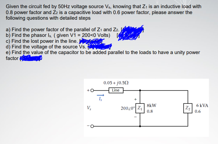
Transcribed Image Text:Given the circuit fed by 50HZ voltage source Vs, knowing that Z, is an inductive load with
0.8 power factor and Z2 is a capacitive load with 0.6 power factor, please answer the
following questions with detailed steps
a) Find the power factor of the parallel of Zı and Z2.
b) Find the phasor Is. ( given Vi = 200<0 Volts)
c) Find the lost power in the line.
d) Find the voltage of the source Vs.
e) Find the value of the capacitor to be added parallel to the loads to have a unity power
factor
0.05 + jo.50
Line
8kW
6 kVA
20020° Z1
0.8
0.6
Expert Solution
This question has been solved!
Explore an expertly crafted, step-by-step solution for a thorough understanding of key concepts.

Step by step
Solved in 6 steps with 1 images

Knowledge Booster


Learn more about
Need a deep-dive on the concept behind this application? Look no further. Learn more about this topic, electrical-engineering and related others by exploring similar questions and additional content below.Recommended textbooks for you
Power System Analysis and Design (MindTap Course …
Electrical Engineering
ISBN:
9781305632134
Author:
J. Duncan Glover, Thomas Overbye, Mulukutla S. Sarma
Publisher:
Cengage Learning
Power System Analysis and Design (MindTap Course …
Electrical Engineering
ISBN:
9781305632134
Author:
J. Duncan Glover, Thomas Overbye, Mulukutla S. Sarma
Publisher:
Cengage Learning