Group 29 Introduction Waste Heat Recovery (WHR) is a process to transform waste heat into useful work. This can be applied to various industrial processes, which produce waste heat over a wide range of temperatures [1]. In internal combustion engines, only 30-35% of the energy provided by fuel is converted to mechanical power, with the remaining two thirds of the fuel energy lost to the environment as heat via the coolant and exhaust gas [1]. Amongst different thermodynamic cycles, Organic Rankine Cycle (ORC) is considered as a viable technology for the WHR system. The ORC is the same as other conventional cycle energy systems (e.g. steam) but uses organic fluids such as refrigerants (e.g. R134a). Compared to the subcritical operating condition, the ORC system wringing under supercritical conditions has potential to improve the cycle thermal efficiencies up to 10-15%. Furthermore, the ORCS can be used in both mobile (e.g. trucks) and stationary applications (combined heat and power plants). ORC-WHR Figure 1 depicts an ORC-WHR system with multiple heat sources for stationary applications. The system has the capability of working in both subcritical and supercritical conditions. Liquid refrigerant at high pressure (state 3) goes through the three heat exchangers (state 4, 5 and 6). These heat exchanges are connected to three heat sources, which represent different (low, medium and high) grades waste heat available in industry. After the high-heat exchanger (state 6), the vapour refrigerant at high temperature and high pressure enters a turbine, which is connected to a generator and produces electricity. The refrigerant then goes into a regenerator (state 7). Here, the vapour refrigerant gives the remaining energy (which could not be extracted by the turbine) to the cold liquid refrigerant, which leaves the compressor (in process 2-3). A low temperature vapour then leaves the regenerator at state 8 and goes into a condenser, where it will be converted to liquid. Finally, the condensed liquid enters the compressor at state 1 and the cycle repeats. Heat source 3 Heat exchanger 3 Compressor Heat source 2 Heat exchanger 2 Organic Rankine Cycle Condenser Pranarod hy Yinwei Cheng Tturbine, inlet Pheat exchanger (°C) (bar) 180 30 8 2 Heat source 1 Heat exchanger 1 Regenerator 3 65 O Cooling water Figure 1 An ORC-WHR with multiple heat sources [1]. Turbine P condenser ncompressor nturbine mrefrig (%) (%) (kg/s) (bar) 5 0.4 82 G Generator Tw.cond.in (°C) 12.5 Tw.cond,out (°C) 25
Group 29 Introduction Waste Heat Recovery (WHR) is a process to transform waste heat into useful work. This can be applied to various industrial processes, which produce waste heat over a wide range of temperatures [1]. In internal combustion engines, only 30-35% of the energy provided by fuel is converted to mechanical power, with the remaining two thirds of the fuel energy lost to the environment as heat via the coolant and exhaust gas [1]. Amongst different thermodynamic cycles, Organic Rankine Cycle (ORC) is considered as a viable technology for the WHR system. The ORC is the same as other conventional cycle energy systems (e.g. steam) but uses organic fluids such as refrigerants (e.g. R134a). Compared to the subcritical operating condition, the ORC system wringing under supercritical conditions has potential to improve the cycle thermal efficiencies up to 10-15%. Furthermore, the ORCS can be used in both mobile (e.g. trucks) and stationary applications (combined heat and power plants). ORC-WHR Figure 1 depicts an ORC-WHR system with multiple heat sources for stationary applications. The system has the capability of working in both subcritical and supercritical conditions. Liquid refrigerant at high pressure (state 3) goes through the three heat exchangers (state 4, 5 and 6). These heat exchanges are connected to three heat sources, which represent different (low, medium and high) grades waste heat available in industry. After the high-heat exchanger (state 6), the vapour refrigerant at high temperature and high pressure enters a turbine, which is connected to a generator and produces electricity. The refrigerant then goes into a regenerator (state 7). Here, the vapour refrigerant gives the remaining energy (which could not be extracted by the turbine) to the cold liquid refrigerant, which leaves the compressor (in process 2-3). A low temperature vapour then leaves the regenerator at state 8 and goes into a condenser, where it will be converted to liquid. Finally, the condensed liquid enters the compressor at state 1 and the cycle repeats. Heat source 3 Heat exchanger 3 Compressor Heat source 2 Heat exchanger 2 Organic Rankine Cycle Condenser Pranarod hy Yinwei Cheng Tturbine, inlet Pheat exchanger (°C) (bar) 180 30 8 2 Heat source 1 Heat exchanger 1 Regenerator 3 65 O Cooling water Figure 1 An ORC-WHR with multiple heat sources [1]. Turbine P condenser ncompressor nturbine mrefrig (%) (%) (kg/s) (bar) 5 0.4 82 G Generator Tw.cond.in (°C) 12.5 Tw.cond,out (°C) 25

Principles of Heat Transfer (Activate Learning with these NEW titles from Engineering!)
8th Edition
ISBN:9781305387102
Author:Kreith, Frank; Manglik, Raj M.
Publisher:Kreith, Frank; Manglik, Raj M.
Chapter5: Analysis Of Convection Heat Transfer
Section: Chapter Questions
Problem 5.54P

Related questions
Question
100%
![Group
29
Introduction
Waste Heat Recovery (WHR) is a process to transform waste heat into useful work. This can
be applied to various industrial processes, which produce waste heat over a wide range of
temperatures [1]. In internal combustion engines, only 30-35% of the energy provided by fuel
is converted to mechanical power, with the remaining two thirds of the fuel energy lost to the
environment as heat via the coolant and exhaust gas [1]. Amongst different thermodynamic
cycles, Organic Rankine Cycle (ORC) is considered as a viable technology for the WHR
system. The ORC is the same as other conventional cycle energy systems (e.g. steam) but
uses organic fluids such as refrigerants (e.g. R134a). Compared to the subcritical operating
condition, the ORC system wringing under supercritical conditions has potential to improve
the cycle thermal efficiencies up to 10-15%. Furthermore, the ORCS can be used in both
mobile (e.g. trucks) and stationary applications (combined heat and power plants).
ORC-WHR
Figure 1 depicts an ORC-WHR system with multiple heat sources for stationary applications.
The system has the capability of working in both subcritical and supercritical conditions. Liquid
refrigerant at high pressure (state 3) goes through the three heat exchangers (state 4, 5 and
6). These heat exchanges are connected to three heat sources, which represent different (low,
medium and high) grades waste heat available in industry. After the high-heat exchanger
(state 6), the vapour refrigerant at high temperature and high pressure enters a turbine, which
is connected to a generator and produces electricity. The refrigerant then goes into a
regenerator (state 7). Here, the vapour refrigerant gives the remaining energy (which could
not be extracted by the turbine) to the cold liquid refrigerant, which leaves the compressor (in
process 2-3). A low temperature vapour then leaves the regenerator at state 8 and goes into
a condenser, where it will be converted to liquid. Finally, the condensed liquid enters the
compressor at state 1 and the cycle repeats.
(1)
Heat source 3
Heat
exchanger 3
Compressor
14
Pronarod hy Yinwei Cheng
Heat source 2
Condenser
Heat
exchanger 2 5
Organic Rankine Cycle
Tturbine,inlet Pheat exchanger
(°C)
(bar)
180
30
Cooling water
8
2
Heat source 1
Heat
exchanger 1
Regenerator
Figure 1 An ORC-WHR with multiple heat sources [1].
Turbine
P condenser ncompressor nturbine
(%)
(%)
(bar)
5
65
82
G
Generator
mrefrig. Tw.cond.in
(kg/s)
(°C)
0.4
12.5
Tw.cond,out
(°C)
25](/v2/_next/image?url=https%3A%2F%2Fcontent.bartleby.com%2Fqna-images%2Fquestion%2F0280cc21-8041-4b35-83af-094302e775e5%2F6634047c-35dd-4bce-9916-4f326ffc1dd1%2F6lu8x0d_processed.jpeg&w=3840&q=75)
Transcribed Image Text:Group
29
Introduction
Waste Heat Recovery (WHR) is a process to transform waste heat into useful work. This can
be applied to various industrial processes, which produce waste heat over a wide range of
temperatures [1]. In internal combustion engines, only 30-35% of the energy provided by fuel
is converted to mechanical power, with the remaining two thirds of the fuel energy lost to the
environment as heat via the coolant and exhaust gas [1]. Amongst different thermodynamic
cycles, Organic Rankine Cycle (ORC) is considered as a viable technology for the WHR
system. The ORC is the same as other conventional cycle energy systems (e.g. steam) but
uses organic fluids such as refrigerants (e.g. R134a). Compared to the subcritical operating
condition, the ORC system wringing under supercritical conditions has potential to improve
the cycle thermal efficiencies up to 10-15%. Furthermore, the ORCS can be used in both
mobile (e.g. trucks) and stationary applications (combined heat and power plants).
ORC-WHR
Figure 1 depicts an ORC-WHR system with multiple heat sources for stationary applications.
The system has the capability of working in both subcritical and supercritical conditions. Liquid
refrigerant at high pressure (state 3) goes through the three heat exchangers (state 4, 5 and
6). These heat exchanges are connected to three heat sources, which represent different (low,
medium and high) grades waste heat available in industry. After the high-heat exchanger
(state 6), the vapour refrigerant at high temperature and high pressure enters a turbine, which
is connected to a generator and produces electricity. The refrigerant then goes into a
regenerator (state 7). Here, the vapour refrigerant gives the remaining energy (which could
not be extracted by the turbine) to the cold liquid refrigerant, which leaves the compressor (in
process 2-3). A low temperature vapour then leaves the regenerator at state 8 and goes into
a condenser, where it will be converted to liquid. Finally, the condensed liquid enters the
compressor at state 1 and the cycle repeats.
(1)
Heat source 3
Heat
exchanger 3
Compressor
14
Pronarod hy Yinwei Cheng
Heat source 2
Condenser
Heat
exchanger 2 5
Organic Rankine Cycle
Tturbine,inlet Pheat exchanger
(°C)
(bar)
180
30
Cooling water
8
2
Heat source 1
Heat
exchanger 1
Regenerator
Figure 1 An ORC-WHR with multiple heat sources [1].
Turbine
P condenser ncompressor nturbine
(%)
(%)
(bar)
5
65
82
G
Generator
mrefrig. Tw.cond.in
(kg/s)
(°C)
0.4
12.5
Tw.cond,out
(°C)
25
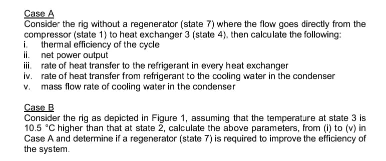
Transcribed Image Text:Case A
Consider the rig without a regenerator (state 7) where the flow goes directly from the
compressor (state 1) to heat exchanger 3 (state 4), then calculate the following:
i. thermal efficiency of the cycle
ii.
net power output
iii.
rate of heat transfer to the refrigerant in every heat exchanger
iv.
rate of heat transfer from refrigerant to the cooling water in the condenser
v. mass flow rate of cooling water in the condenser
Case B
Consider the rig as depicted in Figure 1, assuming that the temperature at state 3 is
10.5 °C higher than that at state 2, calculate the above parameters, from (i) to (v) in
Case A and determine if a regenerator (state 7) is required to improve the efficiency of
the system.
Expert Solution

Step by step
Solved in 9 steps with 3 images

Knowledge Booster


Learn more about
Need a deep-dive on the concept behind this application? Look no further. Learn more about this topic, mechanical-engineering and related others by exploring similar questions and additional content below.Recommended textbooks for you
Principles of Heat Transfer (Activate Learning wi…
Mechanical Engineering
ISBN:
9781305387102
Author:
Kreith, Frank; Manglik, Raj M.
Publisher:
Cengage Learning
Principles of Heat Transfer (Activate Learning wi…
Mechanical Engineering
ISBN:
9781305387102
Author:
Kreith, Frank; Manglik, Raj M.
Publisher:
Cengage Learning