H.W: A steel pipe with an outside diameter of 4.500 in. and an inside diameter of 4.026 in. supports the loadings shown in the figure. Determine: (a) The normal and shear stresses on the top of the pipe at point H. (b) The normal and shear stresses on the side of the pipe at point K. (c) The principal stresses and the magnitude of the maximum in-plane shear stress at point H, and show the orientation of these stresses on an appropriate sketch. (d) The principal stresses and the magnitude of the maximum in-plane shear stress at point K, and show the orientation of these stresses on an appropriate sketch. 3,700 lb-ft 15 in. 2,300 lb 4,200 lb 9 in. FIGURE 1,700 lb
H.W: A steel pipe with an outside diameter of 4.500 in. and an inside diameter of 4.026 in. supports the loadings shown in the figure. Determine: (a) The normal and shear stresses on the top of the pipe at point H. (b) The normal and shear stresses on the side of the pipe at point K. (c) The principal stresses and the magnitude of the maximum in-plane shear stress at point H, and show the orientation of these stresses on an appropriate sketch. (d) The principal stresses and the magnitude of the maximum in-plane shear stress at point K, and show the orientation of these stresses on an appropriate sketch. 3,700 lb-ft 15 in. 2,300 lb 4,200 lb 9 in. FIGURE 1,700 lb

Mechanics of Materials (MindTap Course List)
9th Edition
ISBN:9781337093347
Author:Barry J. Goodno, James M. Gere
Publisher:Barry J. Goodno, James M. Gere
Chapter2: Axially Loaded Members
Section: Chapter Questions
Problem 2.6.17P: Acting on the sides of a stress element cut from a bar in uniaxial stress are tensile stresses of...

Related questions
Question
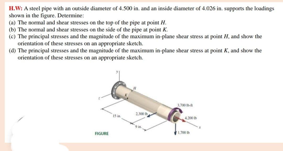
Transcribed Image Text:H.W: A steel pipe with an outside diameter of 4.500 in. and an inside diameter of 4.026 in. supports the loadings
shown in the figure. Determine:
(a) The normal and shear stresses on the top of the pipe at point H.
(b) The normal and shear stresses on the side of the pipe at point K.
(c) The principal stresses and the magnitude of the maximum in-plane shear stress at point H, and show the
orientation of these stresses on an appropriate sketch.
(d) The principal stresses and the magnitude of the maximum in-plane shear stress at point K, and show the
orientation of these stresses on an appropriate sketch.
H.
3,700 Ib-ft
2,300 lb
15 in.
4,200 lb
9 in.
FIGURE
1,700 Ib
Expert Solution
This question has been solved!
Explore an expertly crafted, step-by-step solution for a thorough understanding of key concepts.

This is a popular solution!

Trending now
This is a popular solution!

Step by step
Solved in 6 steps with 6 images

Knowledge Booster


Learn more about
Need a deep-dive on the concept behind this application? Look no further. Learn more about this topic, mechanical-engineering and related others by exploring similar questions and additional content below.Recommended textbooks for you
Mechanics of Materials (MindTap Course List)
Mechanical Engineering
ISBN:
9781337093347
Author:
Barry J. Goodno, James M. Gere
Publisher:
Cengage Learning
Mechanics of Materials (MindTap Course List)
Mechanical Engineering
ISBN:
9781337093347
Author:
Barry J. Goodno, James M. Gere
Publisher:
Cengage Learning