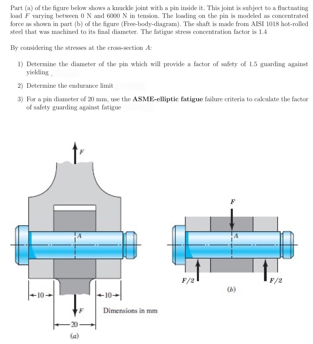
Part (a) of the figure below shows a knuckle joint with a pin inside it. This joint is subject to a fluctuating load F varying between 0 N and 6000 N in tension. The loading on the pin is modeled as concentrated force as shown in part (b) of the figure (Free-body-diagram). The shaft is made from AISI 1018 hot-rolled steel that was machined to its final diameter. The fatigue stress concentration factor is 1.4 By considering the stresses at the cross-section A: 1) Determine the diameter of the pin which will provide a factor of safety of 1.5 guarding against yielding 2) Determine the endurance limit 3) For a pin diameter of 20 mm, use the ASME-elliptic fatigue failure criteria to calculate the factor of safety guarding against fatigue
Part (a) of the figure below shows a knuckle joint with a pin inside it. This joint is subject to a fluctuating load F varying between 0 N and 6000 N in tension. The loading on the pin is modeled as concentrated force as shown in part (b) of the figure (Free-body-diagram). The shaft is made from AISI 1018 hot-rolled steel that was machined to its final diameter. The fatigue stress concentration factor is 1.4 By considering the stresses at the cross-section A: 1) Determine the diameter of the pin which will provide a factor of safety of 1.5 guarding against yielding 2) Determine the endurance limit 3) For a pin diameter of 20 mm, use the ASME-elliptic fatigue failure criteria to calculate the factor of safety guarding against fatigue

Mechanics of Materials (MindTap Course List)
9th Edition
ISBN:9781337093347
Author:Barry J. Goodno, James M. Gere
Publisher:Barry J. Goodno, James M. Gere
Chapter8: Applications Of Plane Stress (pressure Vessels, Beams, And Combined Loadings)
Section: Chapter Questions
Problem 8.5.32P

Related questions

Question
Transcribed Image Text:Part (a) of the figure below shows a knuckle joint with a pin inside it. This joint is subject to a fluctuating
load F varying between 0 N and 6000 N in tension. The loading on the pin is modeled as concentrated
force as shown in part (b) of the figure (Free-body-diagram). The shaft is made from AISI 1018 hot-rolled
steel that was machined to its final diameter. The fatigue stress concentration factor is 1.4
By considering the stresses at the cross-section A:
1) Determine the diameter of the pin which will provide a factor of safety of 1.5 guarding against
yielding
2) Determine the endurance limit
3) For a pin diameter of 20 mm, use the ASME-elliptic fatigue failure criteria to calculate the factor
of safety guarding against fatigue
F
F/2
F/2
(b)
-10-
F
Dimensions in mm
20
(a)
Expert Solution
This question has been solved!
Explore an expertly crafted, step-by-step solution for a thorough understanding of key concepts.

Step by step
Solved in 3 steps with 1 images

Knowledge Booster


Learn more about
Need a deep-dive on the concept behind this application? Look no further. Learn more about this topic, mechanical-engineering and related others by exploring similar questions and additional content below.Recommended textbooks for you
Mechanics of Materials (MindTap Course List)
Mechanical Engineering
ISBN:
9781337093347
Author:
Barry J. Goodno, James M. Gere
Publisher:
Cengage Learning
Mechanics of Materials (MindTap Course List)
Mechanical Engineering
ISBN:
9781337093347
Author:
Barry J. Goodno, James M. Gere
Publisher:
Cengage Learning