haust is the main system exhaust. The zones are to held at 75 °F db / 50% RH when the total heat gain of each one is 200,000 BTUH and the sensible heat ratio is 0.6. Outside air (OA) is 95 °F db / 40% RH and the system is designed to operate with a mass flow rate of dry air that contains 25% OA & 75% RA (return air). The hot deck provides sensible heating only, and the air exits the heating coil at 105 °F db. The cold deck is designed such that air exits the cooling
haust is the main system exhaust. The zones are to held at 75 °F db / 50% RH when the total heat gain of each one is 200,000 BTUH and the sensible heat ratio is 0.6. Outside air (OA) is 95 °F db / 40% RH and the system is designed to operate with a mass flow rate of dry air that contains 25% OA & 75% RA (return air). The hot deck provides sensible heating only, and the air exits the heating coil at 105 °F db. The cold deck is designed such that air exits the cooling

Refrigeration and Air Conditioning Technology (MindTap Course List)
8th Edition
ISBN:9781305578296
Author:John Tomczyk, Eugene Silberstein, Bill Whitman, Bill Johnson
Publisher:John Tomczyk, Eugene Silberstein, Bill Whitman, Bill Johnson
Chapter45: Domestic Refrigerators And Freezers
Section: Chapter Questions
Problem 4RQ: Typical head pressures should correspond to a condensing temperature_________ F higher than room...

Related questions
Question
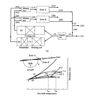
The figure below shows a schematic of a dual-duct system
For design purposes, suppose the zones shown are two of five zones, each having identical operating design conditions. The only exhaust is the main system exhaust. The zones are to held at 75 °F db / 50% RH when the total heat gain of each one is 200,000 BTUH and the sensible heat ratio is 0.6. Outside air (OA) is 95 °F db / 40% RH and the system is designed to operate with a mass flow rate of dry air that contains 25% OA & 75% RA (return air). The hot deck provides sensible heating only, and the air exits the heating coil at 105 °F db. The cold deck is designed such that air exits the cooling coil at 50 °F db / 90 % RH. Take the pressure to be one standard atmosphere.
a. Accurately sketch and label the state points on an electronic psych chart (in particular make sure that the coil is represented as a collie on the TRANE pscyh chart software you can input a coil process)
b. Compute the mass flow rate (lbma/hr) through the heating coil
c. Determine the heating coil capacity (BTUH)
d. Compute the mass flow rate (lbma/hr) through the cooling coil
e. Determine the cooling coil capacity (TONS)
Transcribed Image Text:(8A)
(3M)
(14)
Mixing
box
(64)
Zone A
(24)
(HB)
(38)
(18)
Mixing
bor
Zone R
(28)
(68)
(2)
(2E)
(6)
(2R)
(5) Supply
fan
(4)
Cooling coil
(0)
(8)
(7)
Humidifier Heating coil
(a)
Zone A
Space condition lines
Zone B
SHR
Ahiaw
,7,8
14
-2R, 2
28
18
Dry-bulb temperatlure
Humidity ratio
Expert Solution
This question has been solved!
Explore an expertly crafted, step-by-step solution for a thorough understanding of key concepts.

Step by step
Solved in 2 steps

Knowledge Booster


Learn more about
Need a deep-dive on the concept behind this application? Look no further. Learn more about this topic, mechanical-engineering and related others by exploring similar questions and additional content below.Recommended textbooks for you
Refrigeration and Air Conditioning Technology (Mi…
Mechanical Engineering
ISBN:
9781305578296
Author:
John Tomczyk, Eugene Silberstein, Bill Whitman, Bill Johnson
Publisher:
Cengage Learning

Principles of Heat Transfer (Activate Learning wi…
Mechanical Engineering
ISBN:
9781305387102
Author:
Kreith, Frank; Manglik, Raj M.
Publisher:
Cengage Learning
Refrigeration and Air Conditioning Technology (Mi…
Mechanical Engineering
ISBN:
9781305578296
Author:
John Tomczyk, Eugene Silberstein, Bill Whitman, Bill Johnson
Publisher:
Cengage Learning
Principles of Heat Transfer (Activate Learning wi…
Mechanical Engineering
ISBN:
9781305387102
Author:
Kreith, Frank; Manglik, Raj M.
Publisher:
Cengage Learning