How did you get the I1A and 12A answer pls need the solving thanks

Chapter3: Magnetic Starters
Section: Chapter Questions
Problem 30SQ

Related questions

Question
How did you get the I1A and 12A answer pls need the solving thanks
Transcribed Image Text:11:23:33
(58
Answered: Solve...
bartleby.com
& ASK
퇴 CHAT
SEARCH
νX MAΤΗ '
BSME
bartleby certified
YEAR LEVEL
Step 1
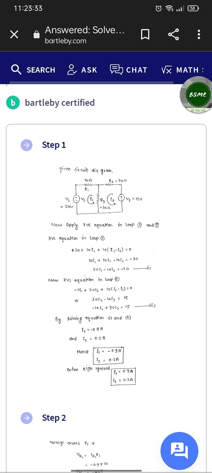
given cii cuit dia giam,
R2 = 20n
RI
= 20v
=lon
Now Apply kul equaton in Loop © nd @
KVL equatton in loop ©
+20+ 101, + 1o( I,-12) = 0
lof, + 1o1, - 10l, = - 20
201, -1012 = -20
Now
KVL equatibn in Loop ©
-15 + 2012 + locl,-11) =0
3012- los, = Is
-10s, + 3012 - 15
By Sdlving equation is and di)
I, =-09 A
and
I, = 0-2 A
Hen ce
f, = - 0.9 A
2 = 0:2A
when sigh ignored
I, = 09A
2 = 0'2A
Step 2
Vel tago acyoss Rj →
VR, = R,PI
-0.9 x 10
Expert Solution
This question has been solved!
Explore an expertly crafted, step-by-step solution for a thorough understanding of key concepts.

Step by step
Solved in 3 steps with 3 images

Knowledge Booster


Learn more about
Need a deep-dive on the concept behind this application? Look no further. Learn more about this topic, electrical-engineering and related others by exploring similar questions and additional content below.Recommended textbooks for you