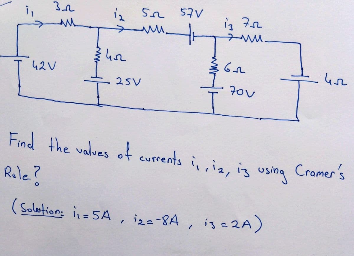
i, 3_22 M 42 V 12 5 3452 57V M. www.tr (Solution: ₁=5A 25V " Find the values of currents 1₁, 12, 13 i,, Role? 13 752 www. i₂=-8A, ≤65 70v using 13 = 2A) ил Cramer's


Q: Given the following FM modulator, if the modulating signal m(t) is given below: (a) Sketch the…
A: According to the question, for the FM signal(a) Sketch the input message signal m(t).(b) Determine…
Q: 2πη A data sequence is given by X[n] = Cos²: + 2 where n = 0, 1, ------7, find the FFT sequence. 16
A:
Q: 1. Derive the transfer function (Eo(s)/E:(s)) of the electrical circuit shown in Figure 1.
A: For the given circuit the transfer function of the circuit needs to be calculated and the same can…
Q: 6. Find i(t) for t>0 in the circuit shown below. 10 Ω 30 V (+ Μ t=0 40 Ω ww 60 Ω ell i(t) 1 mF 2.5 Η
A: The given circuit isWe need to determine the expression of i(t) for t > 0.
Q: 2 NNN The following figure shows a tank with three discrete sensors; pressure switch, level switch,…
A: The following figure shows a tank with three discrete sensors : pressure switch, level switch and…
Q: Question 3 [5] The current in the circuit below is known to be i(t) = B₁e-2000 cos (1500t) +…
A: The current in the circuit is given as,The equation of natural current response in under damped is…
Q: Find voltage v(t), t>= 0, across the capacitor and plot v(t).
A:
Q: Part a) Find the phase shift of the circuit Part b) Determine the phase shift is leading or lagging…
A: In this question, we need to determine the phase shift of the input voltage and output voltage. Also…
Q: Problem 1 (continued) (c) Complete the table below. w (rads-¹) 0 H(s) 40 40 x 106 = V₂(s) V₁(s)…
A:
Q: 2) In the circuit shown below, find the Z and Y-parameters. 10 Ω X Μ V₁ X 10 Ω Μ 10 Ω Μ 10 Ω Μ Y V₂…
A: In this question, we need to determine the Z and Y parameters.
Q: Consider the circuit shown below for this problem. 10 ΚΩ 120 V + a VC 0, and the expression for the…
A: The voltage across a capacitor will not change suddenly unless an impulse source is applied.Under…
Q: 1) For the circuit shown in fig. 1, V₁= 0.7v, μnCox= 100 μA/v², L= 1μm & W= 32 μm. a) Design for lp=…
A:
Q: On the antenna of a receiver, the following tank is observed: L=55uH, C= variable trimer a) If the…
A: The above question is based on an antenna based on an LC oscillator.Given:L = 55 μHfrequency f = 1.2…
Q: 10 V QA (+1 392 www 7F 292 1=0
A:
Q: The switch in the circuit shown below has been in position 1 for a long time before moving to…
A: The circuit diagram,
Q: A light dimming circuit has a light bulb in series with an adjustable circuit element: an inductor,…
A:
Q: A 50kHz sinusoidal voltage has zero phase angle and a maximum amplitude of 10mV. When this voltage…
A:
Q: a) Draw the signal flow graph. b) Find the transfer function G(s)= C(s)/R(s) of the system using…
A: For the given block diagram the equivalent signal flow graph needs to be drawn and the transfer…
Q: Determine the system that produced the following Bode Plot: Magnitude (dB) Phase (deg) 50 45 40 35…
A: Given:a bode plot, we need to determine the system function
Q: Initial conditions in a capacitor are important because Group of answer choices Capacitor voltage…
A: The initial conditions in a capacitor are important because of the nature of how capacitors store…
Q: Tutorial Q1: Find the minimum sampling rate that can be used to obtain samples that completely…
A: According to guidelines soving only one ques at a time1)Find the minimum sampling rate that can be…
Q: The op amp circuit shown is ideal. The values for the circuit are as follows: +VCC = 12.0V, -VCC =…
A: Since you have post question with multiple sub so we will do first 3 for you.Parameters,VCC =…
Q: 4. The armature of a four-pole DC generator has 90 slots on its armature with 6 conductors per slot.…
A:
Q: 3. Obtain the exponential Fourier series of the function in Fig.3 f(t) 5 Fig.3 0 1 2 3 5 t
A:
Q: An active dipole in open circuit has a voltage of 120v and in short circuit it has a current of 25A.…
A: The active dipole can be seen as an ideal voltage source with an internal resistance. When it's in…
Q: A resistor of 20 Ohms and a capacitance of unknown value when connected in in parallel across a…
A:
Q: What is the Laplace transform of the following signal? x (t) = e −2(t−1) cos(t — 1)u(t – 1)
A: The objective of the question is to find the Laplace transform of the given signal x(t) =…
Q: What is the step response, i.e., y(t) for x(t) = u(t), of the system with the following transfer…
A: For the given system, the step response of the system needs to be obtained in the time domain. The…
Q: Obtain the Fourier series of v2() in the waveform
A: As asked in the question, we'll solve only part (b).Given:a signal,we need to compute Fourier…
Q: X(z)= -1 2+2z -1 4-z¹+2z -2
A:
Q: 2. For the circuit shown below, + VR R=792 V = 0.35cos(at) V V₁ XL Xc = = 50 Ω (a) Find the value of…
A: “Since you have posted a question with multiple sub-parts, we will solve first three sub-parts for…
Q: If the voltage across a circuit of constant resistance is doubled, how is the circuit affected?
A: The question is asking about the effect on a circuit when the voltage across it is doubled, while…
Q: Q4/ A modulated signal (4 cos 212π × 10³t+4 сos2π × 94000t) applied to a synchronous detector, if…
A:
Q: 14. Referring to the circuit in the following figure. Find V(t) for t>0. 492 1 H m 2u(-1) A (+…
A: Given that for t<0, the supply for the circuit is only the current source because the voltage…
Q: Consider the series circuit comprising of the diode and a resistor whose value is shown on the…
A: The circuit is given asThe supply voltage is given as
Q: 16. Calculate i(t) for t>0 in the circuit shown below. 20u(-t) V (+ 592 + V- F - i P T
A:
Q: The output of a CT is a ___ 1. DC voltage 2. a torque for driving an indicator 3. an AC voltage
A: The output of a CT (Current Transformer) is typically an AC (alternating current) voltage. CTs are…
Q: 1. Obtain the Fourier series expansion for the waveform shown in Fig. 1. Fig. 1 F -πT 7 0 Т -14 N 2T…
A:
Q: Determine the equivalent resistance of the association, the current is the potential difference, in…
A: Given circuit:Asked to find the,Total equivalent resistance?The voltages and currents in the…
Q: The transfer function for a circuit is V₂ (s) 120 V₁(s) s + 40 Design a circuit using resistors,…
A:
Q: 10v2 www lov ·lov Τζον www 52 ww 2 los 40v
A: Regarding this inquiryAs the circuit indicates, we must ascertain the current flowing through the 5…
Q: Example 1: The equation of an angle modulated signal is: PFM (t) = 10 cos(10³t + 3 sin 10¹t) volts…
A:
Q: Solve for Im 16.72A 10.84A 28A 12.67 A
A: In the given circuit the value of the current through the motor needs to be calculated and the same…
Q: Problem 3 L in(t) mm + v₁ (t) (a) Find the driving-point impedance, Z(s) = V₁(s)/I₁(s) (b) Find the…
A: In this question, we need to determine the driving impedance and transfer function of the given…
Q: Given the following FM modulator, if the modulating signal m(t) is given below: (a) Sketch the…
A:
Q: Complete the truth table for the CMOS circuit shown by entering 0 or 1 for each missing value of Z…
A:
Q: Problems 1 Generate the following sequences using the basic MATLAB signal functions and the basic…
A: The objective of the question is to generate two sequences using MATLAB and comment on the waveform…
Q: a) Redraw the circuit in the frequency domain b) Write an expression for V(s) using circuit laws c)…
A:
Q: Comparator - Home Work What will be the output waveform if the (Vin) at inverting input? VN VREF…
A:
Q: How many multiplication and addition is required to calculate all the samples of auto-correlated…
A: The objective of the question is to determine the number of multiplications and additions required…

Step by step
Solved in 6 steps with 6 images


- please help me dont copy from google In a 250 km long, interphase voltage of 154 kV, 50 Hz three-phase transmission line, the diameter of the steel core aluminum conductors is 22 mm, the roughness coefficient of the conductors is 0.8, and the spacing between the phases is 4 m. Average air temperature along the line is 27 degrees, air pressure is 750 mm Hg. Calculate the total corona loss per phase at 1.5 times the operating voltage under these conditions (E0=21.2 kV/cm)A single phase, 50Hz transmission line connected between two buses having line resistance of 3Ω, inductive reactance of 0.2 Henry. Both the ends of transmission lines are connected with series capacitors of 400microfarads each for series compensation. Then series impedance of the line is a.(3-j31) Ω b.(3-j59.6) Ω c.(3+j31)Ω d.(3+j59.6) Ω 2- Fast decoupled algorithm is not as accurate as the exact Newton Raphson algorithm for Variable number of iteration Fixed number of iteration Variable time per iteration Fixed time per iterationA load line of infinite length is located at y = 3, z = 5; if ρL = 30nC / m. FindE at a) the origin, b) A (0,6,1); c) B (5,6,1).ANS .: - 47.6 ay - 79.3 az N / m; 64.7 ay - 86.3 az N / m; 64.7 ay - 86.3 az N / m
- please help solve part c , d and e A 350-km 450-kV, 60-Hz three-phase uncompensated line has a series reactance x=0.34 Ω/km and shunt admittance y=j 6.5 x 10 -6 S/km (positive-sequence). Calculate,(a) Characteristic impedance Zc(b) (γl)(c) The exact ABCD parameters of the line. (d) The wavelength λ in km.(e) The SIL in MW.An energy transmission line with a length of 130 km transmits 150MVA of power at 380 kV voltage. The conductors used have a conductivity of 35 [m / mm mm²] and a diameter of 28.11mm. The final temperature reached by this transmission line is 66 degrees. (NOTE = temperature coefficient of conductor a20deg = 0.00403deg ^ -1) Approximately how many kWatts is the total loss in the three-phase line at 20 degrees?Question 3) A 350-km 450-kV, 60-Hz three-phase uncompensated line has a series reactance x = 0.34 Q2/km and shunt admittance y=j 6.5 * 10 ^ - 6 S/km (positive-sequence). Calculate, (a) Characteristic impedance Zc (b) (yl) (c) The exact ABCD parameters of the line. (d) The wavelength X in km. (e) The SIL in MW.
- 60 Hz three-phase transmission line, Each single phase transmission line consists of two hard-drawn aluminium conductors with a radius of 2 cm spaced 1.2m apart. It delivers 150 MW at 220 KV at the receiving end with a power factor of 0.88 lagging. If the transmission line is 30 Km long and the temperature of the conductors is 20 C. Ignore the skin effect and consider the resistivity of Aluminium is (2.83 x 10⁻⁸), and permeability of free space, u= 4pi*10-7 N/A2 and permeability of it is= 8.85x10⁻¹² F/m. - Find total series impedance. - Find total shunt admittance. - Find the voltage at the sending end using long-line equation.TOPIC: Transmission Lines, Power Systems, and Powerplants:INSTRUCTIONS:- Answer in this format: Given, Illustration, Required Conversion, Solution, Final Answer.- Step-by-step solution, do not skip even simple calculations to avoid confusion.- If answered in written form, make sure it is readable.PROBLEM:The per-phase constants of a 345-kV, three-phase, 150-km-long transmission line are resistance = 0.112/km, inductance-1.1 mH/km, and capacitance = 0.02 uF/km. The line supplies a 180-MW load at 0.9 power factor lagging. Using the nominal-m circuit, determine the sending-end voltage in kV. 351.2 349.3 348.7 350.8Calculate the total operating cost of a lossless system for a total load of 2000 MW. Thefuel-cost curves for two generators are given as,c(P) = 700 +18P, +0.06(P)?c2(P2) = 900+ 22P2 + -0.03 (P2)a) 122887.88 $/hrb) 153872.65 $/hrc) 124196.22 $/hrd) 138622.16 $/hr
- 1/In the Transmission Line Simulator, the Transmission Line is connected in Nominal-Pi Circuit. Select one: True Falsehe parameters of the 500km long transmission line are impedance z = 0.1 + j * 0.4ohm / km and admintance Y = j * 4.2 Siemens / km. At the end of the line, 988.1A current is drawn under 400kV voltage between phases. The angle of the current is -68.6 degrees. In which option the characteristic impedance value of the long transmission line is given correctly. a) 400 + j * 0 b) 441,23-j * 25,7520 c) 0 + j * 400 d) 401,23-j * 250 e) 310,97-j * 38,282A 30 mile, 3-phase transmission line delivers 8,000 kW at 33 kV, p.f. 0.8 lagging. The resistance and reactance of single conductor are 0.6 ohm and 0.72 ohm respectively per mile. Find the voltage at the sending end in kV.