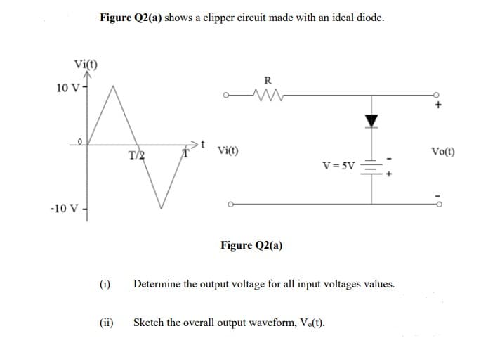
(i) Determine the output voltage for all input voltages values. (ii) Sketch the overall output waveform, Vo(t).


Q: -jue I2 V2 Sind yu
A:
Q: Homework: Determine the output C for the system represented in figure below: R G G2 H. R
A:
Q: Complete the membership table to show (AUB) - (AnB) = B,
A: AND gate- It's output is high only when both the inputs are high, if not then output is low. OR…
Q: Find the transfer function G(s) I(s) for the electric circuit shown V(s) %3D which contains a…
A: Given: The electric circuit is shown below: It contains a nonlinear resistor whose V-I relationship…
Q: K(s - 5) G(s) = s2 – 4s + 29 where K is a positive scaling factor. 1. Determine the pole(s), and…
A:
Q: What characteristics of the thermistor make it a flexible temperature transducer?
A: Thermistor : Thermistor is a type of resistor which is temperature dependent which resistance…
Q: Answer the following: A) Type of clipper circuit per level of clipping. 1. ___________ 2.…
A: A) Type of clipper circuit on the basis of level of clipping. Positive clipper - this clipper clips…
Q: . A 400-amp circuit breaker protects a feeder that's installed in a nonmetallic raceway that…
A: Answer: A. No.1
Q: A single phase half-wave AC voltage controller provides output RMS voltage of 50V when the…
A: Steps to find the output RMS voltage First find the supply voltage using given output rms and…
Q: 22 22 10V I1 13 12V I2 12 I4 62 15 12V 5V 32 32 +
A: Mesh analysis:
Q: A rectangular waveguide is filled with a (non-magnetic) perfect dielectric. The metal is a PEC. X &…
A:
Q: Sketch the transfer curve for an n-channe depletion type MOSFET with IDSS=10 mA and Vp = -8 V
A:
Q: An op amp is designed to be
A: An op amp is designed to be:
Q: As an engineer working in ABABA Sdn. Bhd., you are required to design a packaging process based on…
A: Thermistor: A thermistor is a resistive device made up of metal oxides encased in epoxy or glass and…
Q: Find the total work done when a charge Inc moving From point ( 1,2,4) to a point (-1,3,4) if E = 2ax…
A: In this question, We need to determine the total work done If a charge move from one point to…
Q: Determine i using Thevenin's Theorem. 202 -Ww 140V (±) (↑) 18 A
A: The solution is given below
Q: Use the Y-Y circuit shown below, a)Solve for the phase voltage at load end b)Solve for the phase…
A: In this question we need a)Solve for the phase voltage at load end b)Solve for the phase current.
Q: Home workl: A short-shunt compound generator delivers a load current of 30 A at 220 V, and has…
A: Since you have asked multiple questions in a single request, we will be answering only the 1st…
Q: In the emitter follower, the output (emitter) voltage is 0.7V below the input (base) voltage. One…
A: Given emitter follower And The output (emitter) voltage is 0.7V below the input (base) voltage. One…
Q: Use the Y-Y circuit shown below. What is the phase angle of the line voltage (Vab) at the load end?…
A: In this question, We need to determine the the phase angle of the line voltage (Vab) at the load…
Q: IDSS = 20 mA and VGS(off) = -6 V for a particular JFET. (a) What is ID when VGS = 0 V? (b) What is…
A:
Q: 8. If we convert PPM to PWM & then detect the message signal, will the o/p has less distortion? 9.…
A: Pulse Position Modulation(PPM): Pulse Location Modulation is a modulation technique that allows for…
Q: Find the resistance of a circular wire that is 0.5-m long with radius of 1mm and has a resistivity…
A:
Q: 1. Sketch the output waveform of the given circuit in Figure 1. The peak voltage is 20V with 50HZ…
A: In this question we need to draw a output voltage waveform for the given half wave rectifier.
Q: 24 V 12 N 56 N 8 A 24 2
A: We need to find current for given circuit.
Q: USING THEVENIN'S THEOREM FIND THE CURRENT FLOWING THROUGH Z2. SHOW YOUR THEVENIN'S EQUIVALENT…
A:
Q: a- Phase angle equal zero b- The applied voltage lead the current by 90°. c- The average power equal…
A: We are authorized to answer the first question since the exact one wasn’t specified. Please submit a…
Q: In the circuit, determine: a) I, VR and VC in phasor form b) The total power factor, and indicate…
A: As per the guidelines of Bartley we supposed to answer first three subpart only.
Q: An ac circuit represented in the time domain and in the frequency domain is shown in the circuit.…
A:
Q: For the circuit shown, determine: a) The impedances Z1 and Z2 in polar form b) The combined total…
A: We represent the given circuit in phasor domain.
Q: Which substrate does an p-channel made device possess? O a. None of options Ob. Both P & N-type O c.…
A:
Q: - Determine an alternative method for implement the full-adder. Hint: Write the expressions of the…
A: We need to design Full adder circuit .
Q: Diagram the floor plan for the main floor of your home. Locate the service entrance panel. If it is…
A: Here, We have to design the floor plan for the main floor of home.
Q: Duct banks for medium- and high-voltage feeders are identified with _______ on top before final…
A: In this case, the identification of the duct banks with medium and high voltage feeders needs to be…
Q: In the figure, find the Thevenin equivalent circuit 2v 600 N 9 cos 500t 1/150 mF 300 2 +
A:
Q: ketch the transfer curve for an n-channel epletion type MOSFET with IDSS=10 mA nd Vp = -8 V %3D
A:
Q: When designing the MOSFET, the minimum feature size is the smallest dimension possible to…
A: Answer: True
Q: 1 Tx(t) 14.
A:
Q: D2 D3 R1 = 12 kN Dí D4 Figure 2. Circuit for problem 5 and 6 che bridge rectifier shown in Figure 2…
A: Please refer the attached images for the complete answer..
Q: If a 0.5H inductance rated 110v is to be operated at a source of 230v. At what value of resistance…
A: Given data, Inductance L = 0.5 H Inductive voltage VL=110 V Source voltage Vs=230 V Let frequency is…
Q: D2.6. In each of the following parts, find a numerical value for div D at the point specified: (a) D…
A:
Q: A three – phase 11 kV wye connected synchronous alternator has a synchronous reactance of 8 ohms per…
A:
Q: Compare the bandwidth of BASK and BFSK?
A:
Q: If a 0.5H inductance rated 110v is to be operated at a source of 230v. At what value of resistance…
A: In this question, We need to determine the value of resistance must be connected in series with…
Q: Draw variable capacitor and label it's parts
A:
Q: 9. Assume 10 mC point charge at the origin in free space. Calculate at P(6, 5, 4) if V 5 V at N(2,…
A: The solution is given below
Q: D2 2K he circuit shown, determine the voltage across resistor R2. your answer 1.5V he circuit shown,…
A:
Q: SSB transmission contains 800 W. This transmission is to be replaced by a standard AM signal with…
A: We need to find out power in carrier and power in side band of modulated signal
Q: A Platinum RTD thermometer has a resistance of 136 ohms at 90 degrees celsius,if it's resistance…
A: Given, R1 = 136 ohm at T1 = 90c, R0 = 100 ohm at T0 = 0c, To calculate the temperature at which R1…
Q: Determine the current flowing and the power dissipated across 4-2 resistor using Source…
A: The solution is given below


Trending now
This is a popular solution!

Step by step
Solved in 3 steps with 3 images


- How is a solid-state diode tested? Explain.Suppose we have a 10-V-peak sinusoidal voltage source. Draw the diagram of a circuit that clips off the part of the sinusoid above 5 V and below -4 V. The circuit should be composed of ideal diodes, dc voltage sources, and other components as needed. Be sure to label the terminals across which the clipped output waveform vo(t) appears.While constructing a Bridge rectifier, the designer mistakenly has swapped the terminals of D3 as shown in the figure below, where • Diode D3 is damaged so that it is always open circuit regardless of the applied voltage. • vs(t) is a sinusoidal signal with a peak value (Vs = 5 V). • Diodes are modelled using the constant voltage model with VDO = 0.7 V • The ac line voltage has an rms value of 120 V and a frequency (f) = 60 Hz • The resistance RL = 10 kohm. a) Calculate the transformer turns ratio (N1/N2) if vs(t) is obtained from the secondary side of the transformer whose primary side is connected to the ac line voltage (which has a 120 V rms value). b) Plot in the same graph the input signal vs(t) and the output signal vout(t) (show all details including amplitudes, time instances, etc.) c) Calculate the rms values of the output signal vout(t). (hint: sin2 (x) = 0.5(1- cos(2x))) d) If a capacitor C = 3.58 µF is connected across R = 10 kohm, repeat (b) in a new graph e) With the…
- While constructing a Bridge rectifier, the designer mistakenly has swapped the terminals of D3 as shown in the figure below, where • Diode D3 is damaged so that it is always open circuit regardless of the applied voltage. • vs(t) is a sinusoidal signal with a peak value (Vs = 5 V). • Diodes are modelled using the constant voltage model with VDO = 0.7 V • The ac line voltage has an rms value of 120 V and a frequency (f) = 60 Hz • The resistance RL = 10 kohm. a) Calculate the transformer turns ratio (N1/N2) if vs(t) is obtained from the secondary side of the transformer whose primary side is connected to the ac line voltage (which has a 120 V rms value). b) Plot in the same graph the input signal vs(t) and the output signal vout(t) (show all details including amplitudes, time instances, etc.) Please plot the graph. c) Calculate the rms values of the output signal vout(t). (hint: sin2 (x) = 0.5(1- cos(2x))) d) If a capacitor C = 3.58 µF is connected across R = 10 kohm, repeat (b) in a new…A diode has a reverse saturation current of 5 x 10-15 A and an ideality factor of 1. If its DC operating voltage is 0.70 V and it is operating at 300°K, what is its small signal resistance in ohms? Express your answer to two decimal places.In the given circuit, (diodes will be considered ideal.a) Draw the V0 output by calculating it according to the input.b) Calculate the average and effective value of the V0 output.c) What are the advantages and disadvantages of using two diodes and two resistors instead of four diodes?Input signal Vm = ± 10V (peak to peak), T = 2π (period), R = 32k
- Consider the circuit below,assuming the diode is ideal:1) When voltage source (Vin) provides a positive voltage, the diode isequivalent to ____________ circuit2) When voltage source (Vin) provides a negative voltage, the diode isequivalent to ____________ circuit3) Sketch the I-V characteristic of the ideal diode model on the chart below.For the ideal-diode clipper circuit given below, VS = 12.sinωt V. Determine the output voltage Vout and sketch this function. Remove the short circuit between points x and y, and replace it with a 2kΩ Resistor. Find the range of values of VS for; D1 and D2 are OFF D1 is ON and D2 is OFF D1 is OFF and D2 is ON Is it possible for both D1 and D2 to be ON?Suppose we have a 10-Hz sinusoidal voltage source, vin(t). Draw the diagram of a circuit that clamps the positive peaks to -4 V. The circuit should be composed of ideal diodes, dc voltage sources, and other components as needed. List any constraints that should be observed in selecting component values. Be sure to label the terminals across which the clamped output waveform vo(t) appears.
- In the given circuit, (diodes will be considered ideal. a) Draw the V0 output by calculating it according to the input. b) Calculate the average and effective value of the V0 output. c) What are the advantages and disadvantages of using two diodes and two resistors instead of four diodes? Input signal Vm = ± 10V (peak to peak), T = 2π (period), R = 2kA semiconductor diode having ideal forward and reverse characteristics is used in a half-wave rectifier circuit supplying a resistive load of 500 ohm. If the r.m.s. value of the sinusoidal supply voltage is 230 V, determine (i) the r.m.s. diode current and (ii) power dissipated in the load.Given the schematic below, assume D1 and D2 are silicon with forward voltages of 0.7V. Find the following (with solutions) a) Conditions required wherein none of the diodes are conducting b) If both diodes are not conduction, what is Vo? Express in terms of Vi c) Plot the overall relationship of Vo and Vi in the coordinate system shown below. Remember, you are to plot the transfer characteristics of the circuit.