(i) Which connection does the positive terminal of the battery have to be connected to for the LED to glow - A or B? (ii) If the LED is glowing, calculate the value of resistor R so the current is 10 mA when the battery has a voltage of 6 V. (iii) Calculate the power dissipated in the resistor for the conditions outlined in ii). (iv) If the resistor has a power rating of 0.125 W, what is the largest voltage that may be applied to the tester? (v) Add an additional LED to the above circuit such that it will indicate when the other terminal of the battery is positive. Draw the new circuit.
(i) Which connection does the positive terminal of the battery have to be connected to for the LED to glow - A or B? (ii) If the LED is glowing, calculate the value of resistor R so the current is 10 mA when the battery has a voltage of 6 V. (iii) Calculate the power dissipated in the resistor for the conditions outlined in ii). (iv) If the resistor has a power rating of 0.125 W, what is the largest voltage that may be applied to the tester? (v) Add an additional LED to the above circuit such that it will indicate when the other terminal of the battery is positive. Draw the new circuit.

Introductory Circuit Analysis (13th Edition)
13th Edition
ISBN:9780133923605
Author:Robert L. Boylestad
Publisher:Robert L. Boylestad
Chapter1: Introduction
Section: Chapter Questions
Problem 1P: Visit your local library (at school or home) and describe the extent to which it provides literature...

Related questions

Question
Answer the following questions, iii, iv and v:
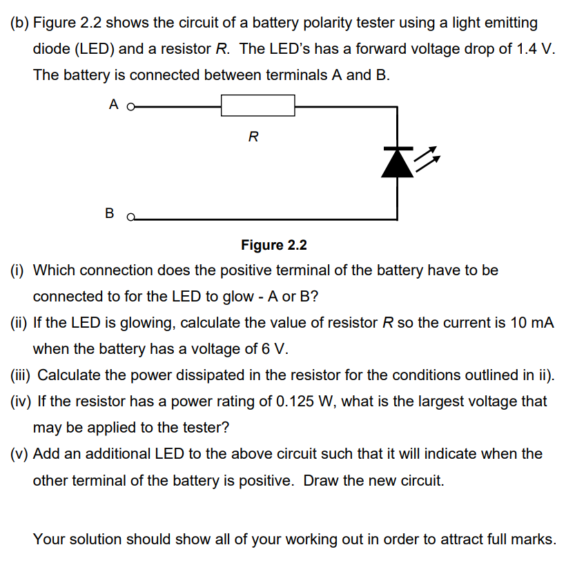
Transcribed Image Text:(b) Figure 2.2 shows the circuit of a battery polarity tester using a light emitting
diode (LED) and a resistor R. The LED's has a forward voltage drop of 1.4 V.
The battery is connected between terminals A and B.
A o
#4
B
R
Figure 2.2
(i) Which connection does the positive terminal of the battery have to be
connected to for the LED to glow - A or B?
(ii) If the LED is glowing, calculate the value of resistor R so the current is 10 mA
when the battery has a voltage of 6 V.
(iii) Calculate the power dissipated in the resistor for the conditions outlined in ii).
(iv) If the resistor has a power rating of 0.125 W, what is the largest voltage that
may be applied to the tester?
(v) Add an additional LED to the above circuit such that it will indicate when the
other terminal of the battery is positive. Draw the new circuit.
Your solution should show all of your working out in order to attract full marks.
Expert Solution
This question has been solved!
Explore an expertly crafted, step-by-step solution for a thorough understanding of key concepts.

Step by step
Solved in 4 steps with 9 images

Knowledge Booster


Learn more about
Need a deep-dive on the concept behind this application? Look no further. Learn more about this topic, electrical-engineering and related others by exploring similar questions and additional content below.Recommended textbooks for you
Introductory Circuit Analysis (13th Edition)
Electrical Engineering
ISBN:
9780133923605
Author:
Robert L. Boylestad
Publisher:
PEARSON

Delmar's Standard Textbook Of Electricity
Electrical Engineering
ISBN:
9781337900348
Author:
Stephen L. Herman
Publisher:
Cengage Learning

Programmable Logic Controllers
Electrical Engineering
ISBN:
9780073373843
Author:
Frank D. Petruzella
Publisher:
McGraw-Hill Education
Introductory Circuit Analysis (13th Edition)
Electrical Engineering
ISBN:
9780133923605
Author:
Robert L. Boylestad
Publisher:
PEARSON
Delmar's Standard Textbook Of Electricity
Electrical Engineering
ISBN:
9781337900348
Author:
Stephen L. Herman
Publisher:
Cengage Learning
Programmable Logic Controllers
Electrical Engineering
ISBN:
9780073373843
Author:
Frank D. Petruzella
Publisher:
McGraw-Hill Education

Fundamentals of Electric Circuits
Electrical Engineering
ISBN:
9780078028229
Author:
Charles K Alexander, Matthew Sadiku
Publisher:
McGraw-Hill Education

Electric Circuits. (11th Edition)
Electrical Engineering
ISBN:
9780134746968
Author:
James W. Nilsson, Susan Riedel
Publisher:
PEARSON

Engineering Electromagnetics
Electrical Engineering
ISBN:
9780078028151
Author:
Hayt, William H. (william Hart), Jr, BUCK, John A.
Publisher:
Mcgraw-hill Education,