i. Estimate the value of total inductance between terminals A – B for the circuit shown in Figure B3. 3H Figure B3 ii. If A-B terminals are connected to 150V, 60HZ supply, Estimate the following: a. Energy stored in the inductor coil when a current of 6mA collapses uniformly to 3mA. b. EMF induced in the coil if the time changes from 4ms to 2.5ms
i. Estimate the value of total inductance between terminals A – B for the circuit shown in Figure B3. 3H Figure B3 ii. If A-B terminals are connected to 150V, 60HZ supply, Estimate the following: a. Energy stored in the inductor coil when a current of 6mA collapses uniformly to 3mA. b. EMF induced in the coil if the time changes from 4ms to 2.5ms

Delmar's Standard Textbook Of Electricity
7th Edition
ISBN:9781337900348
Author:Stephen L. Herman
Publisher:Stephen L. Herman
Chapter17: Resistive-inductive Series Circuits
Section: Chapter Questions
Problem 2PA: You are a journeyman electrician working in an industrial plant. Your task is to connect an inductor...

Related questions
Question
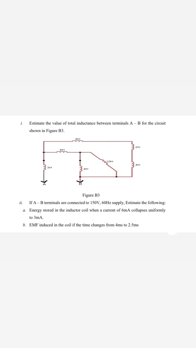
Transcribed Image Text:i.
Estimate the value of total inductance between terminals A - B for the circuit
shown in Figure B3.
Figure B3
ii.
If A - B terminals are connected to 150V, 60HZ supply, Estimate the following:
a. Energy stored in the inductor coil when a current of 6mA collapses uniformly
to 3mA.
b. EMF induced in the coil if the time changes from 4ms to 2.5ms
Expert Solution
This question has been solved!
Explore an expertly crafted, step-by-step solution for a thorough understanding of key concepts.

Step by step
Solved in 3 steps with 3 images

Knowledge Booster


Learn more about
Need a deep-dive on the concept behind this application? Look no further. Learn more about this topic, electrical-engineering and related others by exploring similar questions and additional content below.Recommended textbooks for you
Delmar's Standard Textbook Of Electricity
Electrical Engineering
ISBN:
9781337900348
Author:
Stephen L. Herman
Publisher:
Cengage Learning
Delmar's Standard Textbook Of Electricity
Electrical Engineering
ISBN:
9781337900348
Author:
Stephen L. Herman
Publisher:
Cengage Learning