If R1 = 1Q, R2 = 2 Q, R3=1.5 2, E = 6 V, RG = 0.1 Q, and Rx = 30, what would be the Current reading on the ammeter shown in the circuit below? R2 RG Ammeler E Rx R3
If R1 = 1Q, R2 = 2 Q, R3=1.5 2, E = 6 V, RG = 0.1 Q, and Rx = 30, what would be the Current reading on the ammeter shown in the circuit below? R2 RG Ammeler E Rx R3

Electricity for Refrigeration, Heating, and Air Conditioning (MindTap Course List)
10th Edition
ISBN:9781337399128
Author:Russell E. Smith
Publisher:Russell E. Smith
Chapter13: Heating Control Devices
Section: Chapter Questions
Problem 28RQ

Related questions

Question
100%
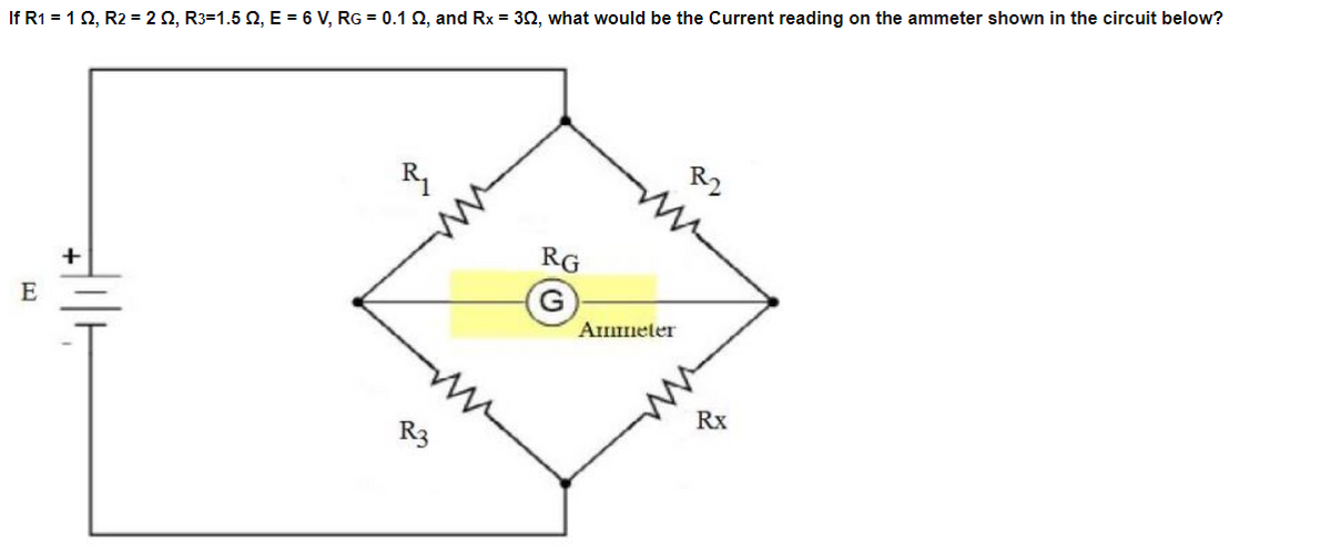
Transcribed Image Text:If R1 = 1Q, R2 = 2 0, R3=1.5 2, E = 6 V, RG = 0.1 2, and Rx = 30, what would be the Current reading on the ammeter shown in the circuit below?
R2
RG
Ammeter
E
Rx
R3
Expert Solution
This question has been solved!
Explore an expertly crafted, step-by-step solution for a thorough understanding of key concepts.

Step by step
Solved in 3 steps with 2 images

Knowledge Booster


Learn more about
Need a deep-dive on the concept behind this application? Look no further. Learn more about this topic, electrical-engineering and related others by exploring similar questions and additional content below.Recommended textbooks for you
Electricity for Refrigeration, Heating, and Air C…
Mechanical Engineering
ISBN:
9781337399128
Author:
Russell E. Smith
Publisher:
Cengage Learning
Electricity for Refrigeration, Heating, and Air C…
Mechanical Engineering
ISBN:
9781337399128
Author:
Russell E. Smith
Publisher:
Cengage Learning