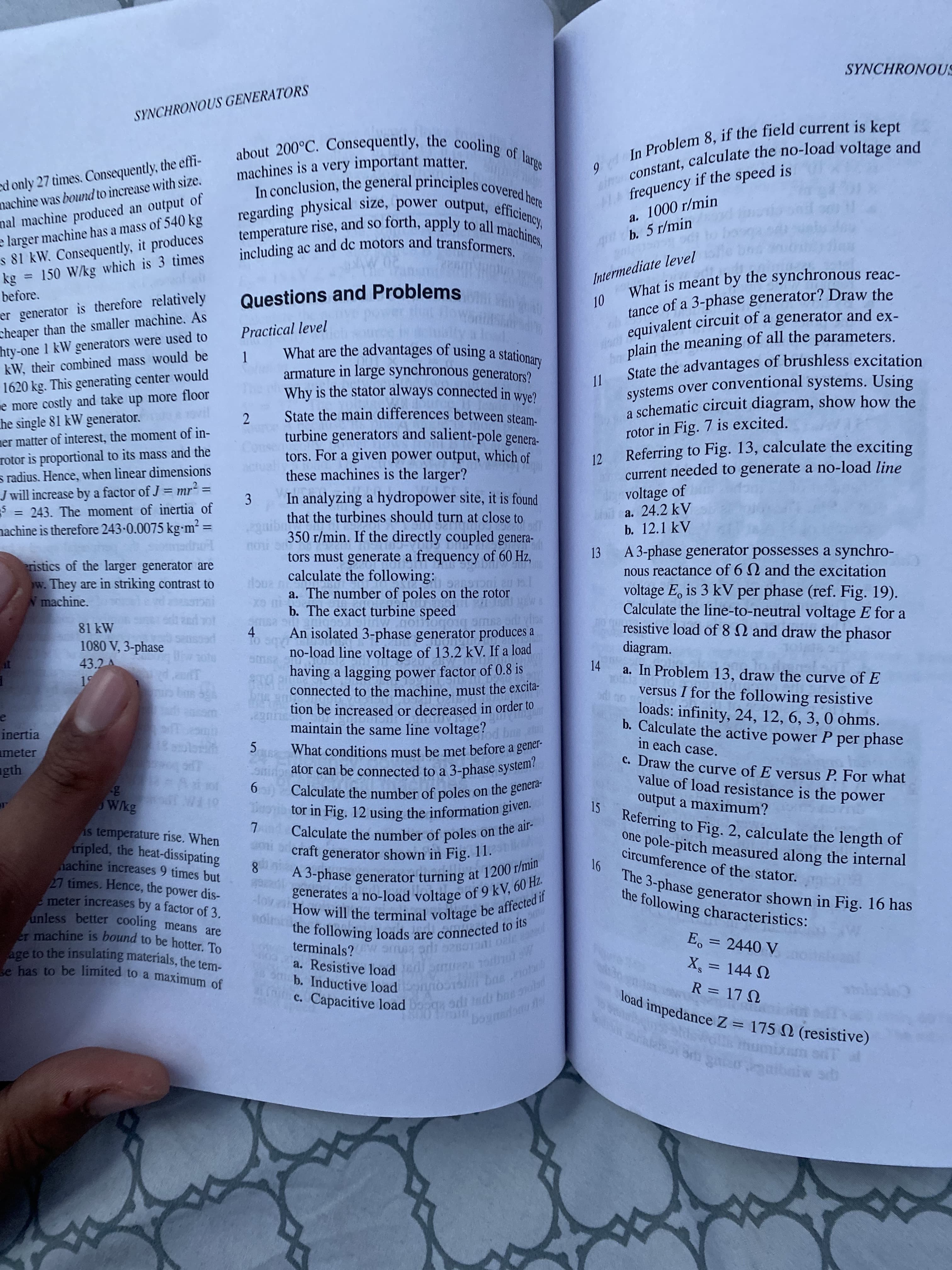
In analyzing a hydropower site, it is found guibe that the turbines should turn at close to 350 r/min. If the directly coupled genera- 3 no tors must generate a frequency of 60 Hz, calculate the following: a. The number of poles on the rotor b. The exact turbine speed An isolated 3-phase generator produces a 4
In analyzing a hydropower site, it is found guibe that the turbines should turn at close to 350 r/min. If the directly coupled genera- 3 no tors must generate a frequency of 60 Hz, calculate the following: a. The number of poles on the rotor b. The exact turbine speed An isolated 3-phase generator produces a 4

Power System Analysis and Design (MindTap Course List)
6th Edition
ISBN:9781305632134
Author:J. Duncan Glover, Thomas Overbye, Mulukutla S. Sarma
Publisher:J. Duncan Glover, Thomas Overbye, Mulukutla S. Sarma
Chapter4: Transmission Line Parameters
Section: Chapter Questions
Problem 4.31P: Figure 4.37 shows the conductor configuration of a three-phase transmission line and a telephone...

Related questions

Question
Number 3
Transcribed Image Text:9 In 8, if the is kept
constant, the and
c. load sdi tndr bae ad
b. load basotb
a. Resistive Tol
equivalent of a and ex-
tance of a 3-phase Draw the
plain the of all the parameters.
terminals? W ama orli oale
SYNCHRONOUS
SYNCHRONOUS GENERATORS
ed only 27 times. Consequently, the effi-
nachine was bound to increase with size.
nal machine produced an output of
e larger machine has a mass of 540 kg
s 81 kW. Consequently, it produces
= 150 W/kg which is 3 times
machines is a very important matter.
frequency if the speed is
a. 1000 r/min
b. 5 r/min
Intermediate level
What is meant by the synchronous reac-
of a 3-phase generator? Draw the
%3D
before.
Questions and Problems
er generator is therefore relatively
cheaper than the smaller machine. As
hty-one 1 kW generators were used to
kW, their combiìned mass would be
01
Practical level
What are the advantages of using a stationary
1.
plain the meaning of all the parameters.
armature in large synchronous generators?
Why is the stator always connected in wye?
2.
State the main differences between steam.
1620 kg. This generating center would
me more costly and take up more floor
he single 81 kW generator. 1Ovil
mer matter of interest, the moment of in-
rotor is proportional to its mass and the
s radius. Hence, when linear dimensions
J will increase by a factor of J = mr² =
3 = 243. The moment of inertia of
nachine is therefore 243-0.0075 kgm² =
II
turbine generators and salient-pole genera-
tors. For a given power output, which of
these machines is the larger?
a schematic circuit diagram, show how the
rotor in Fig. 7 is excited.
Referring to Fig. 13, calculate the exciting
12
current needed to generate a no-load line
voltage of
lod a. 24.2 kV
b. 12.1 kV
A 3-phase generator possesses a synchro-
nous reactance of 6 N and the excitation
voltage E, is 3 kV per phase (ref. Fig. 19).
Calculate the line-to-neutral voltage E for a
resistive load of 8 N and draw the phasor
diagram.
a. In Problem 13, draw the curve of E
versus I for the following resistive
loads: infinity, 24, 12, 6, 3, 0 ohms.
b. Calculate the active power P per phase
in each case.
3.
In analyzing a hydropower site, it is found
that the turbines should turn at close to
%3D
%3D
350 r/min. If the directly coupled genera-
%3D
ILOU
tors must generate a frequency of 60 Hz,
13
ristics of the larger generator are
w. They are in striking contrast to
W machine.
calculate the following:
a. The number of poles on the rotor
b. The exact turbine speed
81 kW
1080 V, 3-phase
43.2 A
An isolated 3-phase generator produces a
4.
no-load line voltage of 13.2 kV. If a load
pecs
be of
14
having a lagging power factor of 0.8 is
connected to the machine, must the excita-
S c
tion be increased or decreased in order to
maintain the same line voltage?
inertia
ug po
meter
5.
C. Draw the curve of E versus P. For what
value of load resistance is the
output a maximum?
smido ator can be connected to a 3-phase system?
9.
Calculate the number of poles
Wkg
15
power
is temperature rise. When
tripled, the heat-dissipating
nachine increases 9 times but
27 times. Hence, the power dis-
meter increases by a factor of 3.
unless better cooling means are
generator shown in Fig. 11.
circumference of the stator.
8.
the following loads are connected to Ts
terminals? w ama
a. Resistive load
b. Inductive load o
E, 32440 V
has to be limited to a maximum of
X, = 144 N
%3D
R=17 N
umixam s
Srb gatarabaiw s
Expert Solution
This question has been solved!
Explore an expertly crafted, step-by-step solution for a thorough understanding of key concepts.

Step by step
Solved in 2 steps with 1 images

Knowledge Booster


Learn more about
Need a deep-dive on the concept behind this application? Look no further. Learn more about this topic, electrical-engineering and related others by exploring similar questions and additional content below.Recommended textbooks for you
Power System Analysis and Design (MindTap Course …
Electrical Engineering
ISBN:
9781305632134
Author:
J. Duncan Glover, Thomas Overbye, Mulukutla S. Sarma
Publisher:
Cengage Learning
Power System Analysis and Design (MindTap Course …
Electrical Engineering
ISBN:
9781305632134
Author:
J. Duncan Glover, Thomas Overbye, Mulukutla S. Sarma
Publisher:
Cengage Learning