In Fig. 5, D is an ideal diode, and R= 1 kQ. (1) Determ the diode. (2) Calculate the current following through th R 10 V 2 V
In Fig. 5, D is an ideal diode, and R= 1 kQ. (1) Determ the diode. (2) Calculate the current following through th R 10 V 2 V

Delmar's Standard Textbook Of Electricity
7th Edition
ISBN:9781337900348
Author:Stephen L. Herman
Publisher:Stephen L. Herman
Chapter12: Batteries And Other Sources Of Electricity
Section: Chapter Questions
Problem 3PA: An office building uses a bank of 63 lead-acid cells connected in series with a capacity of 80...

Related questions
Question
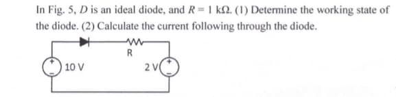
Transcribed Image Text:In Fig. 5, D is an ideal diode, and R = 1 kN. (1) Determine the working state of
the diode. (2) Calculate the current following through the diode.
R
10 V
2 V
Expert Solution
This question has been solved!
Explore an expertly crafted, step-by-step solution for a thorough understanding of key concepts.

Step by step
Solved in 2 steps with 2 images

Knowledge Booster


Learn more about
Need a deep-dive on the concept behind this application? Look no further. Learn more about this topic, electrical-engineering and related others by exploring similar questions and additional content below.Recommended textbooks for you
Delmar's Standard Textbook Of Electricity
Electrical Engineering
ISBN:
9781337900348
Author:
Stephen L. Herman
Publisher:
Cengage Learning
Delmar's Standard Textbook Of Electricity
Electrical Engineering
ISBN:
9781337900348
Author:
Stephen L. Herman
Publisher:
Cengage Learning