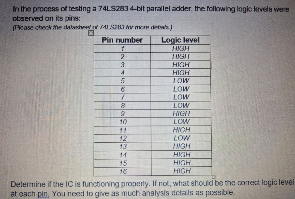
In the process of testing a 74LS283 4-bit parallel adder, the following logic levels were observed on its pins: (Please check the datasheet of 74LS283 for more details.) Pin number 1 Logic level HIGH 2 HIGH 3 HIGH 4 HIGH 5 LOW 6 LOW 7 LOW 8 LOW 9 HIGH 10 LOW 11 HIGH 12 LOW 13 HIGH 14 HIGH 15 HIGH HIGH 16 Determine if the IC is functioning properly. If not, what should be the correct logic level at each pin. You need to give as much analysis details as possible.
Q: Solve the Following Question
A: Below is the clarified and detailed explanation for above tricky question....if you are ok with my…
Q: 1. When the frequency of the input signal to a CMOS gate is increased, the average power dissipation…
A: Since you have posted multiple questions, we will provide the solution only to the first five…
Q: Derive the relation between output signal to noise ratio and input signal to noise ratio for SSB-LC…
A: Single Sideband (SSB) modulation is a technique used in communication systems to transmit…
Q: 1. Consider the following circuit containing two sources, each with an internal resistance of 5 92,…
A: The circuit diagram,
Q: 36. V + ZA + ↑ 6-22 ww ·8i₁ + lov €252 3A ↑ www. 452 202 |ti, 'N+ 152
A:
Q: You are asked to design a DSB-SC modulator to generate a modulated signal Am(t)cos(@t) with the…
A: According to the question, we need to design DSB-SC modulator signal by using Ring modulator.Given…
Q: 12. Given F(a, b, c) = ∑ m(0, 4, 7) What are the ∏ M? __________________________________________
A: Given data:Min terms F(a, b, c) = ∑ m(0, 4, 7),Asked to find the maxterms (∏M) of the…
Q: Assuming the 100-V source is "turned off" and the 1-V test source is connected across terminal A-B,…
A:
Q: How do I solve the problem given below?
A:
Q: Answers are at the end of the chapter. 1. Determine the sum (E) and the output carry (Cout) of a…
A: For the given sets of inputs the output value of the half adder and full adder needs to be…
Q: Why a pull-up resistor is required for an open collector TTL gate or open-drain in C MOS? and when?…
A: Digital logic gates can interface with external circuits or devices, but it's vital to ensure that…
Q: PROBLEM 6. Given the NPN transistor collector characteristic curves, find the active region value of…
A: Given:npn transistor collector characteristic curve,we need to find the active region value of when…
Q: In the circuit shown, the potential difference VA VB = 41.0 V and the resistance R₁ = R₂ = R3 = R4 =…
A: In this question, we need to determine the currents IA and IB as shown in the circuit. We solve this…
Q: The figure below shows five resistors and two batteries connected in a circuit. What are the…
A:
Q: Please explain and draw a 555 timer chip (actual chips drawn with the gate symbols inside)
A: The solution is given below Explanation:
Q: QUESTION 5 01 02 m R₁ R₂ Rg Rf + An ideal op-amp circuit is shown above. Assume that v₁ = 4V, v2 =…
A:
Q: X A uniform plane wave with E = a Ex propagates in a simple lossless medium (€₁. = 4,₂= 1,0 = 0) in…
A:
Q: Problem 2)- The figure below shows the binary input data and carrier signal that used in a optical…
A:
Q: 5 v (+1 1K ww 2.2K www V₁ 3.3K 1K m V₂ www 2.7K
A: Given that, voltage V2 =?
Q: In an AM/DSB-LC modulator, the carrier signal is c(t) = 4 cos(6π107 t) and th m(t) = cos(7000πt).…
A:
Q: ind inverse Fourier Transform
A:
Q: Using the two images attached of a Circuit State What is the Circuit doing and Give an example of…
A: According to the question, based on the given waveform as shown belowWe need to explain the working…
Q: Design a digital circuit which has 4 inputs. The output only accepts combinations of 3 inputs.
A: Y = (ABC) + (ABD) + (ACD) + (BCD)Circuit shown below.Explanation:A digital circuit with four inputs…
Q: 3. For the circuit in the figure, complete: a) The total impedance in polar form. b) The value of…
A: Given circuit-Find:-(a )The total impedance in polar form.(b) Value of capacitor, inductor.(c) Value…
Q: Consider the following function: f(t)=0.25u(t−2)+0.5u(t−4)+1u(t−6)+2u(t−8)+4u(t-10) The Laplace…
A: The question is about finding Laplace transform of f(t).
Q: Find the current gain to R = 36 Ω. + | R Μ 20 Ω +1 10 Ω www 500 40 Ω
A: Compute the value of io/is of the given circuitwhere R=36Ω
Q: Please answer in typing format
A: An operational amplifier (op-amp) is an electronic component designed to amplify voltage signals. It…
Q: Consider a silicon pn junction with ND = 10¹6 cm ³, N₁ = 5 x 10¹5 cm-³, and the cross-sectional area…
A: Below is the clarified and detailed explanation for above tricky question...if you are ok with my…
Q: Many prototype circuits need simulation. One web-based simulation software can be located here -…
A: Please refer below pages.If you have any doubts feel free to ask.Explanation:Step 1: Step 2: Step 3:…
Q: From the following block diagram convert to a Flux diagram, and get its transfer function using…
A: Given block diagram is,Asked to find the transfer function by converting the block diagram to flux…
Q: The switch in the circuit in (Figure 1) has been in position a for a long time. At t = 0, it moves…
A: The given circuit iswhere v1=80 V & v2=130 V.A. We need to determine the values of α and ω for…
Q: Question 2: Using superposition theorem, find the current passing through R, for the circuit of…
A: Using super position theorem calculation of of current passing through resistance R4.According to…
Q: Practice Problem 5.4 Two kinds of current-to-voltage converters (also known as transresistance…
A: Proofs attached for each problemExplanation:(a)(b)
Q: A boost regulator has an input voltage Vs=6V and an average output voltage Va=12V. The average…
A:
Q: Consider a PV module with the following output parameters at STC given by the manufacturer: . PMPP =…
A: This is a question for junction
Q: 5. A voltage source produces a "Triangle" wave and is connected to a series diode and resistor…
A: The given circuit isWe need to determine which graph is best represents the voltage across the…
Q: A thermostat for a central air system will control both a heating and cooling system. When a target…
A: According to the question, we need to design a logic circuit for the given condititon a shown belowA…
Q: 3.17. A 200-turn coil is rotating at a speed of 3600 rpm in a 4-pole generator. The flux per pole is…
A: The given question is solved in step by step process.Explanation:
Q: ◄ Messages Health and Safety Mr Ali Lilo, AL4510222L Time remaining: 55 Quick Select QuestiBiespnds…
A: The correct answer is class 1 ladder that is option (d) is correct. Class 1 ladders are heavy-duty…
Q: An electric field in the xy-plane is Ễ = −åxy — ayx, (volts per unit length). There are two points…
A:
Q: Messages AA - following statements and select the most appropriate answer. Statement one PPE must…
A: The most appropriate answer is:b) Statement one is incorrect and statement two is correct.…
Q: ) Plot the truth table for the following boolean function: F(x, y, z) = x(yz+xz) + y
A: In this question, we need to determine the truth table of the given boolean function. We know, 1+A=…
Q: Use K-map to simplify the following function in SOP (sum of product) and POS (product of sum) form.
A: See picture for solution....Explanation:Step 1: Step 2: Step 3: Step 4:
Q: The supply voltage of the op amp in the circuit is 16 V. If R₁ = 2,3000, assign a resistance value…
A: Given circuit: -Find: -The value of Rf .
Q: Implement the following boolean function using 3x8 decoders :F( x , y , z,w) = Σ m(4,6,10, 12)…
A: Below is the clarified and detailed explanation for above tricky question...if you are ok with my…
Q: 9. Obtain a mathematical model of the circuit shown below: Transfer functions: I/ E and L/E इक 2(1)
A: Given:a circuit,we need to find:Transfer functions,
Q: G(s)H(s) K(s+1) s(s − 1)(s² + 4s + 16) By using second method of Ziegler- Nichols, calculate the PID…
A: Given:considering unity feedback system,we need to find:PID parameters using Zeigler Nichols second…
Q: Given a vector field F = axxy-a, 2x, find its circulation around the path OABO shown in Fig. 2-22.…
A:
Q: The binary sequence 101010111101010100001111 is applied to the DPSK transmitter, by using two…
A: According to the question, the binary sequence 101010111101010100001111 is applied to the DPSK…
Q: Two signals m1 (t) and m2(1), both band-limited to 5000 Hz, are to be transmitted simultaneously…
A: According to the questin, the block diagram of the communication system is shown below as(a) Sketch…
Logic levels
Step by step
Solved in 1 steps with 1 images
- Choose a suitable BCD equivalent of a decimal number (432.56)10 3. Select a suitable logic family, which has extremely low power consumption. a) b) c) d) 0100 0011 0010.0101 0100 0100 0011 0010.0100 0110 0100 0011 0010.0101 0110 None of the aboveI was able to fill out the truth table for part A. I ONLY need help for PART B. B) Implement the logic function (z) using the multiplexer 74HC151 shows in the picture.Act 1 problem solving this is a logic circuits and design laboratory subject please help me with this and screenshot all the solution and answers 2. What is the largest binary number that can be expressed with 16 bits? What are the equivalent decimal and hexadecimal numbers? Answer: 16 bits = ________= _______10 = ______16 3. Represent the decimal number 6,248 in: (a) BCD = (b) excess‐3 code = (c) 2421 code =
- Defferentiate comparatively the analogue and digital representations.(b)if332to base10=x to base8 then find the value of X.(c)1001011.0112 to equivalent decimal (d)what do you know about the logic gates?explain the AND gate in details.) Assume A=A3A2A1A0, and B=B3B2B1B0 , both 4 bit binary numbers. If Y=3A+B, answer the following: Design a digital circuit that implements Y using the minimum hardware. You may use 4 bit adders, Half adders, Full adders, and a minimum number of logic gates as necessary. *(sketch your solution)Design a combinational logic circuit that converts a three-bit binary number from code A to code B, according to the table on the right. Answer the following questions: Code A Code B 000 000 100 001 110 010 010 011 011 100 001 101 101 110 111 111 Implement your circuit using two 2-by-4 decoders (with enables) only. Explain your implementation. You can use as many ‘OR’ gates and inverters as you need. Implement your circuit using 4-by-1 multiplexers and the fewest number of additional logic gates (if needed). Provide the complete implementation.
- Please design a 6:1 multiplexer following the below procedures with data inputs of D5, D4, D3,D2, D1, D0 and output of Y.1 How many select signals are needed for this Mux.2) List a truth table for this Mux. Note: for all the unused combinations of select signals, Y=D5Develop an optimized function for this Mux.4Sketch the logic diagram of implementing this 6:1 Mux. Write a complete VHDL structural model to implement the above 6:1 multiplexer. Assume allthe required sub-component (standard gates) VHDL models are given/known that you can use.Please provide Handwritten answer Question: You must only use DIL chips in your design! No logic gates! 1) 4-bit addition using an 4-bit full adder 74LS83.Simplify the given Boolean expression and then draw a logic circuit using NOR Gates. X (A, B, C, D) = AB’C’ + AC + A’CD’
- 1-Using the Karnaugh Method, design and draw the circuit of the logic circuit that gives the result of the multiplication of the two-bit numbers "AB" and "CD" according to minterms (SOP). Do not make any further simplifications before or after the Karnaugh Method. In tables and Karnaugh, ensure that the least significant bit is on the far right and the entries are sorted alphabetically. Make sure that the circuit you have drawn is understandable, the function you have written and the truth table are readable.Create the logic circuit diagram for zF= X’Y + XZ’DIGITAL LOGICGiven the two binary numbers X = 1000100 and Y = 100101 , perform the subtraction X - Y by using 1's complement and 2's complement.