-j30 Is IL IR Vc Vs j6N ViR 122 Figure QI(b) (b) An ideal voltage source is connected with one resistor, one capacitor, and one inductor as shown in Figure QI(b). The source provides an ideal sinusoidal voltage Vs = 15 V with frequency f= 50 Hz. Underlined quantities are phasors. i) Explain impedance and admittance. Then, caleulate the combined admittance YLR of the resistor and inductor, and the total impedance ZaLR of the resistor, inductor, and capacitor, presented to the voltage source. ii) Explain nodal analysis. Then, using nodal analysis and taking Vs as the reference phasor, calculate the phasor voltages VLR, and Vc. ii) Calculate the phasor currents Is. I and IR.
-j30 Is IL IR Vc Vs j6N ViR 122 Figure QI(b) (b) An ideal voltage source is connected with one resistor, one capacitor, and one inductor as shown in Figure QI(b). The source provides an ideal sinusoidal voltage Vs = 15 V with frequency f= 50 Hz. Underlined quantities are phasors. i) Explain impedance and admittance. Then, caleulate the combined admittance YLR of the resistor and inductor, and the total impedance ZaLR of the resistor, inductor, and capacitor, presented to the voltage source. ii) Explain nodal analysis. Then, using nodal analysis and taking Vs as the reference phasor, calculate the phasor voltages VLR, and Vc. ii) Calculate the phasor currents Is. I and IR.

Power System Analysis and Design (MindTap Course List)
6th Edition
ISBN:9781305632134
Author:J. Duncan Glover, Thomas Overbye, Mulukutla S. Sarma
Publisher:J. Duncan Glover, Thomas Overbye, Mulukutla S. Sarma
Chapter2: Fundamentals
Section: Chapter Questions
Problem 2.27P: An industrial load consisting of a bank of induction motors consumes 50 kW at a power factor of 0.8...

Related questions
Question
!
Transcribed Image Text:-j3N
Is
IL
IR
Vc
Vs
j6N
ViR Ž 122
Figure QI(b)
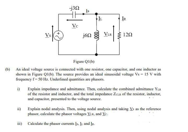
(b) An ideal voltage source is connected with one resistor, one capacitor, and one inductor as
shown in Figure QI(b). The source provides an ideal sinusoidal voltage Vs = 15 V with
frequency f= 50 Hz. Underlined quantities are phasors.
i)
Explain impedance and admittance. Then, calculate the combined admittance YLR
of the resistor and inductor, and the total impedance ZCLR of the resistor, inductor,
and capacitor, presented to the voltage source.
ii) Explain nodal analysis. Then, using nodal analysis and taking Vs as the reference
phasor, calculate the phasor voltages VLR, and Vc.
iii)
Calculate the phasor currents Is. I and IR.
Expert Solution
This question has been solved!
Explore an expertly crafted, step-by-step solution for a thorough understanding of key concepts.

Step by step
Solved in 4 steps with 4 images

Knowledge Booster


Learn more about
Need a deep-dive on the concept behind this application? Look no further. Learn more about this topic, electrical-engineering and related others by exploring similar questions and additional content below.Recommended textbooks for you
Power System Analysis and Design (MindTap Course …
Electrical Engineering
ISBN:
9781305632134
Author:
J. Duncan Glover, Thomas Overbye, Mulukutla S. Sarma
Publisher:
Cengage Learning
Power System Analysis and Design (MindTap Course …
Electrical Engineering
ISBN:
9781305632134
Author:
J. Duncan Glover, Thomas Overbye, Mulukutla S. Sarma
Publisher:
Cengage Learning