source provides a sinusoidal current i,(t) of 60 Hz to two resistors and a capacitor, so that rough this last element circulates a current ic(t). R2 i,(t) ( R1 C rie(t) a) If R2 = 1N , design R1and C so that the effective value of i (t) be half of is (t) and so that the lag between these currents is 45°
source provides a sinusoidal current i,(t) of 60 Hz to two resistors and a capacitor, so that rough this last element circulates a current ic(t). R2 i,(t) ( R1 C rie(t) a) If R2 = 1N , design R1and C so that the effective value of i (t) be half of is (t) and so that the lag between these currents is 45°

Power System Analysis and Design (MindTap Course List)
6th Edition
ISBN:9781305632134
Author:J. Duncan Glover, Thomas Overbye, Mulukutla S. Sarma
Publisher:J. Duncan Glover, Thomas Overbye, Mulukutla S. Sarma
Chapter2: Fundamentals
Section: Chapter Questions
Problem 2.27P: An industrial load consisting of a bank of induction motors consumes 50 kW at a power factor of 0.8...

Related questions
Question
question 2
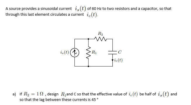
Transcribed Image Text:A source provides a sinusoidal current is (t) of 60 Hz to two resistors and a capacitor, so that
through this last element circulates a current ic(t).
R2
i,(t) (
R1
ric(t)
a) If R2 = 1N , design R1and C so that the effective value of i.(t) be half of is (t) and
so that the lag between these currents is 45°
Expert Solution
This question has been solved!
Explore an expertly crafted, step-by-step solution for a thorough understanding of key concepts.

Step by step
Solved in 4 steps with 4 images

Recommended textbooks for you
Power System Analysis and Design (MindTap Course …
Electrical Engineering
ISBN:
9781305632134
Author:
J. Duncan Glover, Thomas Overbye, Mulukutla S. Sarma
Publisher:
Cengage Learning
Power System Analysis and Design (MindTap Course …
Electrical Engineering
ISBN:
9781305632134
Author:
J. Duncan Glover, Thomas Overbye, Mulukutla S. Sarma
Publisher:
Cengage Learning