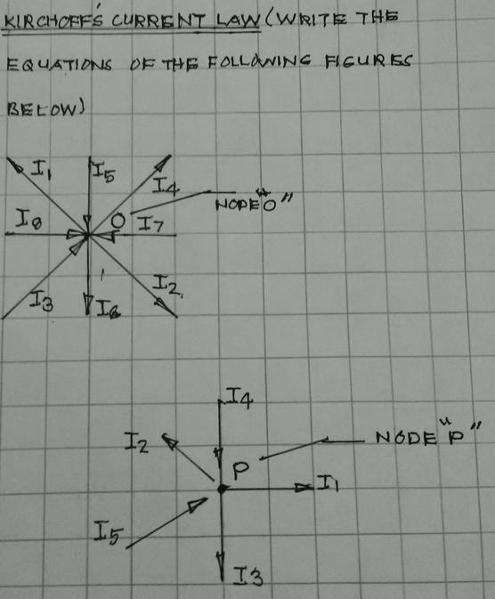
KIRCHOFFS CURRENT LAYW(WRITE THE EQUATIONS OF THE FOLLaNING FIGURES BELOW)


Q: For the DC circuit shown in Figure P30, find the voltage across each resistor and the current in…
A: We have to calculate the voltage and current across each resister.
Q: A docs.google.com . For the circuit shown in figure. For the circuit shown in Figure Vcc Vcc= 22 V,…
A:
Q: + VR - a.) VR 15 ohms IT b.) Vc 450µF + c.) IT Vc 110V/f Xc 7 ohms d.) f e.) ZT
A:
Q: (b) (i) Calculate the cut-off frequency and overall gain for the circuit in Figure Q2(b). (ii)…
A:
Q: Load Shape Load Outside Diameter Length of Load to Heat Solid or Hollow Wall thickness Heating Goal…
A: Given current: 31 A voltage 42V Induction coil measurement: It has 1/8” OD and 0.03” wall…
Q: Find the Thévenin and Norton equivalent circuits for the two-terminal circuit shown in Figure P2.83.
A: Resistance, R1 = 10 Ω Resistance, R2 = 10 Ω Resistance, R3 = 15 Ω Resistance, R4 = 30 Ω Voltage, V =…
Q: Calculate I1,I2, and I3 currents for an ideal opamp in the circuit given in the figure.
A: The explanation is as follows.
Q: As an engineer, select one of the configuration that provides a sustainable solution in terms of…
A: Power Dissipation is one of the undesired parameter in electrical engineering. Every engineer always…
Q: Derive an expression for Voin Figure below in terms of the two inputs V1 and V2. R2 R3 R4 R1 VA VO…
A: Given : Brief description: In the above question we have an electrical circuit which is made up of…
Q: Determine a. the currents Ii, Iz, I, Is, Is, IL, and b. the potential at b, c,d,e, and h jov
A:
Q: V5 IA 30 VA Ž120 +2VA 5A V2 V1 V3 9Ω +)12 V 4 IA
A: I USED QUCS SIMULATION SOFTWER ALL NODE VOLTAGE IS SHOWN IN SIMULATION TABLE.
Q: Fundamentals of Electrical Engineering 2020/2021 Dr. Yaseen H. Tahir Example: For the circuit shown…
A: The answer as given below:
Q: Problem 3.4: A dc source with open-circuit voltage of 120 V drops to 105 V under 15 A load.…
A:
Q: Q3 The block diagram in figure Q3 shows a plant G,(s) controlled by a controller Ge(s) using a unity…
A: Given, Gs=1s2+2s+6
Q: A power suppply having 220 V AC input and two fixed outputs as 10 V DC and 20 V DC is requested from…
A: a) We can design the circuit as b) and c) Output response will be like
Q: QI// Analysis the circuit shown in figure below. SET J2 Q2 CLK K2 X- RESET SET J1 Q1 CLK K1 RESET…
A:
Q: A power suppply having 220 V AC input and two fixed outputs as 10 V DC and 20 V DC is requested from…
A: According to the question, a) Design your power supply and point out DC voltage outputs, b) Explain…
Q: b) Calculate the cut-off frequency and overall gain for the circuit in Figure Q2(b). (ii) Justify…
A:
Q: following Consider FET is idea
A: NOTE- “Since you have posted a question with multiple sub-parts, we will solve first three subparts…
Q: Describe the function of each of the resistors shown.
A: The resistance given in the network are: RI, RG, RD, R3 where RI is the input resistance RG is the…
Q: a) Show that [G Q→P) ^ 4Q→† P]]→Q. What is this composite proposition called? b) A 2-terminal…
A: A 2 terminal element with defining relation (q,v)=0 where q is charge and v is voltage is an…
Q: Q3: The figure shown below is the load curve of a power station. There are two loads have been…
A:
Q: Q3): Analysis the circuit shown in figure below: 1 T Q т Q т Q Clock
A:
Q: 1. Convert the following current source into an equivalent voltage source and redraw the circuit.…
A: As per bartleby expert policy, only one individual question is to be answered.
Q: Consider the following system in open loop:: G(s)= 365 / ( 5 s2 + 39 s + 387 ) Compute the…
A: We need to find steady state value for given system .
Q: For the machine given in the figure has state diagram as, 2-1 MUX Q X1 Y CLK Select A-0 0-6 A-1 A=1…
A: 2 x 1 MUX means multiplexer. From the given logic circuit, A is the select input and when A =0 then…
Q: Q3) What two factors are responsible for the resistance change dR /R in an electrical resistance…
A: An electrical resistance strain gauge depends on the electrical resistivity of any conductor There…
Q: write brief notes on thefollowing expressions node mesh branch local voltage ideal current…
A:
Q: Where can you find a ground in Multisim Live Online Circuit Simulator? а. Electromechanical b.…
A: In Multisim online circuit simulator, Schematic connectors block contains Ground, voltage source,…
Q: X ct) 2 七 -५ -३ 2 2 3 Figure Q2. ca) consider a Con tinu ous signal 8(4) shown in figure &2. Ca) (1)…
A: In this question, x(t) signal graph is given. We need to draw the y(t) using the shifting and…
Q: (b) (i) Calculate the cut-off frequency and overall gain for the circuit in Figure Q2(b). (ii)…
A:
Q: Determine V o for the network of Figure. D1 o V 10 V D2 | R 1 k2 O V Attached your SOLUTION HERE…
A: In this question we need to find a voltage Vo
Q: vcc ŽRC C1 C2 RE
A:
Q: Consider the circuit in Figure 4. a) Find the Thevenin equivalent of the network connected to the…
A:
Q: + vp + -VOL m WHI OVO R R₁
A: From the given Schmit trigger circuit, VTL is the Lower Threshold Limit VTH is the Upper Threshold…
Q: Use the sum of product stragtety to find) 1) The equation 2) Reduce as much as possible 3) The…
A:
Q: The case is pure resistance and the Vdc=10 V, R=10 Q and full time process 4 ms find the out-put…
A: Ans -: we assume logic 1 = switch closed and logic 0 = switch off a) In interval 0 ms<t<1 ms…
Q: Consider the next AC circuit. Use nodal analysis to write an m-file that will calculate: a) the…
A: 1) Apply KVL at node 1…
Q: 1. Explain the importance of power factor correction.
A: It is required explain the importance of power factor correction.
Q: The air conditioner (a kind of vapour-compression refrigerator) in a 1500-cc car, which works on a…
A: Given:mRh2-h1=1.5 KJ/Sp1=2.017 barp2=12 barFrom property table of R-134a,At state 1:h1=hg at 2.017…
Q: ow many different load groups are there in power plants? Explain by drawing on a power-time cu
A: A load following power plant, regarded as producing mid-merit or mid-priced electricity, is a power…
Q: Problem 3: X1 X2 Кур Kịp Tịp Typ TỊp Typ Figure shows a vehicle speed control example block diagram.…
A: Given
Q: Figure Q13 Q14. Obtain the equivalent resistance at the terminals a-b for the circuit in Figure Q14.…
A:
Q: b. Circuit: c. Linear circuit : d. Nonlinear circuit: e. Bilateral
A:
Q: Q3): Analysis the circuit shown in figure below: T Q T. Q T Clock
A:
Q: 50 N 150 2 -> 1:n Vs(t) 200 2 Interface 1 kN Circuit RIN
A: Impedance seen by the source will be 50+(200∥150+1*103n2)....................................(1)…
Subject: Circuits
show your solution please

Step by step
Solved in 3 steps with 3 images

- Find the Value of the impedance only using Ohm law, Kirchhoff Current and Voltage Law and Voltage Curren Divider Thank youHi I will upvote! Please compute for V2. Thanks.low voltage systems In the circuit in the figure, the effective value of the voltage source is V, and the values of the circuit elements are in ohms.What is the current drawn by the coil?a) I = 3, 16–71.54° b) I = 4, 32-45.86° c) I = 7, 33/65, 17 d) I = 4, 52-80, 14°
- Help Please A series circuit has R = 100 ohm L = 50mH and C = 100μF and is supplied with 200V,50Hz. Find (i) Impedance (ii) Current and voltage drop across the each element (iii) power and power factorPlease add that Is is_____ VA is _____ VB is ______ I4 ______Hi I have difficulty solving problems regarding Kirchhoff's Current rule and the voltage rule. I hope you can sove these questions thank you.
- how do i verify my answer for V0 using tellegens theoerm?A device has been tested under different load conditions and load currents have been recorded. Using appropriate techniques, combine the following recorded currents into one single wave i. I1= 0.866SinƟ+0.5CosƟii. I2= 0.574SinƟ-0.819CosƟiii. I3= 0.866CosƟ-0.5SinƟU:21) Determine a voltage divider (as shown below) so that the circuit generate stiff (constant) voltage of 10 v for Rl>10 M ohmusing an ideal dc voltage generator of 30 volt