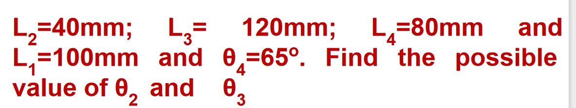
L,=40mm; L,= 120mm; L,=80mm L=100mm and 0,=65°. Find the possible value of 0, and and 0,


Q: Q1) In Fig.(1), the shaft is subjected to a reversed load P = (2700 to - 900) N. Find the length…
A: Given dataLoad P = 2700radius of the filled r = 5Diameter D = 62.5d = 50dH= 6.25To determine the…
Q: 8 kN 8 kN В L 45° 45° 60° A E L D
A:
Q: 1. In figure below, the lower member is of uniform cross section and can be assumed to be rigid.…
A: Given;
Q: Determine the torsion on the rigid supports and the maximum shearing stress developed in each…
A:
Q: The state of stress at a point in a member is shown on the element. Suppose that σx = -50 MPa , σy =…
A: σX=-50MPaσy=-120MPaζxy=-30MPa All stresses are compressive Formula for shear stresses:-…
Q: Two loads P act as shown, one parallel to (x0) and another parallel to z0; each load P equals 1850…
A: GIVEN :- b1=85mmb2=130mmb3=60mmd=28mmP=1850N
Q: 7. The state of stress of an element is given. Determine its principle plane by the specialized…
A: Given Data⇒ σx=24 MPa (Tensile)σy=-38 MPa (Compressive)ζxy=38 MPa
Q: A round Steel rod of 50 mm diameter is bent into an arc of radius 10m. What is the maximum stress in…
A:
Q: The rigid bar ABCD supports point loads at A and D and is being supported by two bars at B and C.…
A: Given data: F1=120 kNF2=90 kN Need to determine the absolute value of the deformation at point C.
Q: L 32 mm L Cross-section K, aran : 17 nam + 6 E= 200 kN/mm m = 15 kg KI= lo kN/m Find f
A:
Q: The bearings at A and D exert only y and z components of force on the shaft as shown in Fig 7.…
A:
Q: If the allowable normal stress is 120MPa and the allowable shear stress is 60MPa, what is the…
A: Allowable normal stress = 120 Mpa Allowable shear stress = 60 Mpa Answer : (a) 8.39 N
Q: 1. Sketch a free-body diagram of each element in the figures. F = 0.8 kN 100 lbf 12 in 60° -A- 6 in…
A:
Q: 5. Find the approximate shear stress
A: To find approximate shear stress developed Exact shear stress developed deformation of the spring
Q: The 200-mm square aluminum block supports a compressive load of 300 kN. 300 kN - 30°
A: ANs FBD Σfx = 0 (Na/a - 300.cos 30°=0 Na-a =…
Q: No Normal stress acts on the neutral axis. Is it true or false? How?
A: When a beam is subjected to a bending moment the beam undergoes either hogging or sagging. In both…
Q: The state of stress at a point in a member is shown in Figure Q1(a). Determine the stress components…
A:
Q: ximum tensil X1
A: given:length l=400mmthickness b=20mmdepth d=80mm
Q: Mohr's circle for an element is shown, each grid is 5 MPa square. A rotated plane through the…
A:
Q: a. Use Mohr's Circle to determine the maximum shear stress on the element b. Also, using Mohr's…
A: Mohr's circle for, σx=-30MPaσy= 50MPaτxy= 20MPa
Q: (a) Find the reactive torques at the supports, TA and TB. Use numerical values as follows: da = 2.3…
A:
Q: If each grid in Mohrs circle below is 15 MPa then the maximum principal stress is: I grid square =…
A:
Q: 30 kN/m 45 kN-m B A- -1.5 m– -1.5 m- -1.5 m- Figure 01(c)
A:
Q: If the steel rod shown is acted upon as shown, Compute for the total deformation of the rod. Assume…
A:
Q: The 12 kN.m torque is applied to the free end of the 5-m steel shaft. The angle of rotation of the…
A:
Q: As shown in the figure below, determine the internal loadings at points A,B and. Consider the…
A:
Q: Q2: The rigid beam shown in fig2 is held by two vertical rods at A and C.If a 60 KN load is applied…
A:
Q: 2. A shaft is made of bronze at length AB and steel at length BC fixed at both ends. It is subjected…
A:
Q: Please simply sketch the shear stress diagram 0.5 in. 0.6 in. 0.d in. / 0.8 in. 0.2 in. 0.6 in. ||B
A: GIVEN: To Sketch the Shear Stress Diagram.
Q: QI/ In figure (a) , the weight of the gate is 12KN and the gate width is 2m. Find the force on the…
A: Given data: The weight of the gate is W=12 kN The width of the gate is b=2 m The height of the gate…
Q: C250x30- 50 mm 350mm -Х C200x20.5
A:
Q: Q1: In the figure. Determine the FB? If EMA = 0 23.5 kN 1.5 m B 9.81 kN 2 m-
A: Given data as per question Force applied at end of the structure = 23.5 KN Force acting at mid of…
Q: Problem #3: Determine the shear strain yry at corners A and B if the plastic distorts as shown by…
A:
Q: If the allowable normal stress is 120MPa and the allowable shear stress is 60MPa, what is the…
A:
Q: Two plates 10 mm thick are joined by single rive 20 mm and pitch = 60 mm. If g, = 125 N/mm², t = 80
A:
Q: 30° 10 kN 4 m B E 4 m 16 kN -3 m -
A:
Q: The assembly consists of three steel rods (E=13 x 10° psi) and a rigid bar AC. The cross-sectional…
A: Given data: Lengths and area of cross-section of 3 steel rods: lAB=6 ft ; AAB=1.3 in2lCD=4 ft ;…
Q: The homogeneous bar ABC is supported by a pin at C and a cable that runs from A to B around the…
A: Draw the free-body diagram of the given beam.
Q: 33 kNA 35 kN 40 kN 45 kN 50 kN 55 kN ww 009 ww 00t
A:
Q: B 4 ft C. E D 20 kips 5 ft- -5 ft-
A:
Q: What is the Shear Force,V?
A: To define: The shear force. Concept used: Shear force: Shear force is an internal force in any…
Q: A shaft is required to fail when the torque on the shaft is 182 N-m. Find the suitable diameter of…
A:
Q: Calculate normal and shear strains at the center
A:
Q: Calculate the stress parallel to the inclined plane AB. Report your answer as a positive number.…
A:
Q: 16000 Psi. (a) Find the inside diameter "d" if the outside diameter is equal to 12 inches. (b) Find…
A: The modulus of rigidity of the hollow steel shaft is, G=12×106 Psi The torque transmitted by the…
Q: find the principal stress , maximum in plane shear stress
A:
Q: The circular shaft is subjected to cyclic load. The Shaft is subjected to maximum load of 500 kN and…
A:
Q: 2. If 75 N/mm is the maximum shear stress and 50 kN-m is the torque acting on a solid shaft, then…
A: Given: Maximum shear stress τmax = 75 N/mm2 = 75000 kN/m2 Torque acting on a shaft T = 50kN-m…

Step by step
Solved in 2 steps with 2 images

- -7 Repeat Problem 2.3-5, but n include the weight of the bar. See Table I-I in Appendix I for the weight density of steel.Repeat Problem 11.3-9. Use two C 150 × 12.2 steel shapes and assume that E = 205 GPa and L = 6 m.A steel riser pipe hangs from a drill rig located offshore in deep water (see figure). (a) What is the greatest length (meters) it can have without breaking if the pipe is suspended in the air and the ultimate strength (or breaking strength) is 550 MPa? (b) If the same riser pipe hangs from a drill rig at sea, what is the greatest length? (Obtain the weight densities of steel and sea water from Table M, Appendix I. Neglect the effect of buoyant foam casings on the pipe.)
- Solve the preceding problem (W 250 × 44.8) if the resultant force P equals 110 kN and E = 200 GPa.Solve the preceding problem for the following data: diameter LO m, thickness 48 mm, pressure 22 MPa, modulus 210 GPa. and Poisson's ratio 0.29.17 A mountain-bike rider going uphill applies torque T = Fd(F = l5lb, d = 4 in.) to the end of the handlebars ABCD by pulling on the handlebar extenders DE. Consider the right half of the handlebar assembly only (assume the bars are fixed at the fork at A). Segments AB and CD are prismatic with lengths L, = 2 in.andL3 = 8.5 in, and with outer diameters and thicknesses d01 = 1.25 in. 101 = 0.125 in. and d03 = O.87in.,i03 = 0.ll5in, respectively as shown. Segment BC’ of length L, = 1.2 in. however. is tapered, and outer diameter and thickness vary linearly between dimensions at B and C. Consider torsion effects only. Assume G = 4000 ksi is constant. Derive an integral expression for the angle of twist of half of the handlebar tube when it is subjected to torque T = Fd acting at the end. Evaluate ‘b1-, for the given numerical1ues.
- Repeat Problem 3.3-1, but now use a circular tube with outer diameter d0= 2.5 in. and inner diameter di= 1.5 in.Compare the angle of twist 1 for a thin-walled circular tube (see figure) calculated from the approximate theory for thin-walled bars with the angle of twist 2 calculated from the exact theory of torsion for circular bars, Express the ratio 12terms of the non-dimensional ratio ß = r/t. Calculate the ratio of angles of twist for ß = 5, 10, and 20. What conclusion about the accuracy of the approximate theory do you draw from these results?A cylindrical brick chimney of height H weighs w = 825 lb/ft of height (see figure). The inner and outer diameters are d1= 3 ft and d2= 4 ft, respectively. The wind pressure against the side of the chimney is p = 10 lb/ft2 of projected area. Determine the maximum height H if there is to be no tension in the brickwork.