Late support reactions in A and C, re force at point A:

Mechanics of Materials (MindTap Course List)
9th Edition
ISBN:9781337093347
Author:Barry J. Goodno, James M. Gere
Publisher:Barry J. Goodno, James M. Gere
Chapter2: Axially Loaded Members
Section: Chapter Questions
Problem 2.2.18P: The horizon Lai rigid beam A BCD is supported by vertical bars BE and CF and is loaded by vertical...

Related questions

Question
need help
Transcribed Image Text:Qb
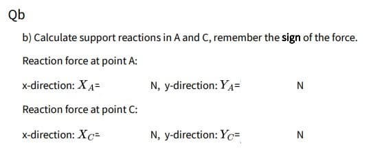
b) Calculate support reactions in A and C, remember the sign of the force.
Reaction force at point A:
x-direction: XA=
N, y-direction: YA=
N
Reaction force at point C:
x-direction: Xc=
N, y-direction: Yc=
N
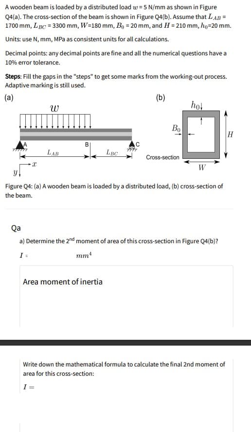
Transcribed Image Text:A wooden beam is loaded by a distributed load w = 5 N/mm as shown in Figure
Q4(a). The cross-section of the beam is shown in Figure Q4(b). Assume that LAB =
1700 mm, LBC = 3300 mm, W=180 mm, B, = 20 mm, and H = 210 mm, ho=20 mm.
%3D
Units: use N, mm, MPa as consistent units for all calculations.
Decimal points: any decimal points are fine and all the numerical questions have a
10% error tolerance.
Steps: Fill the gaps in the "steps" to get some marks from the working-out process.
Adaptive marking is still used.
(a)
(b)
hot
Во
H
B
LAB
LBC
Cross-section
W
Figure Q4: (a) A wooden beam is loaded by a distributed load, (b) cross-section of
the beam.
Qa
a) Determine the 2nd moment of area of this cross-section in Figure Q4(b)?
I =
mm
Area moment of inertia
Write down the mathematical formula to calculate the final 2nd moment of
area for this cross-section:
I =
Expert Solution
This question has been solved!
Explore an expertly crafted, step-by-step solution for a thorough understanding of key concepts.

Step by step
Solved in 2 steps with 2 images

Knowledge Booster


Learn more about
Need a deep-dive on the concept behind this application? Look no further. Learn more about this topic, mechanical-engineering and related others by exploring similar questions and additional content below.Recommended textbooks for you
Mechanics of Materials (MindTap Course List)
Mechanical Engineering
ISBN:
9781337093347
Author:
Barry J. Goodno, James M. Gere
Publisher:
Cengage Learning
Mechanics of Materials (MindTap Course List)
Mechanical Engineering
ISBN:
9781337093347
Author:
Barry J. Goodno, James M. Gere
Publisher:
Cengage Learning