
Concept explainers
Videos
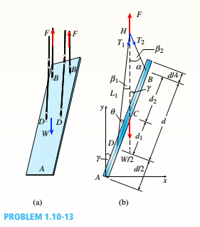
A large precast concrete panel for a warehouse is raised using two sets of cables at two lift lines, as shown in the figure part a. Cable 1 has a length L1 = 22 Ft, cable 2 has a length L2= 10 ft, and the distance along the panel between lift points Band D is d = 14 ft (see figure part b). The total weight of the panel is W = 85 kips. Assuming the cable lift Forces F at each lift line are about equal, use the simplified model of one half of the panel in figure part b to perform your analysis for the lift position shown. Find the required cross-sectional area AC of the cable if its breaking stress is 91 ksi and a factor of safety of 4 with respect to failure is desired.

Trending nowThis is a popular solution!

Chapter 1 Solutions
Mechanics of Materials (MindTap Course List)


- A plane truss is subjected to loads 2P and P at joints B and C, respectively, as shown in the figure part a. The truss bars are made of two L 102 X 76 X 6.4 steel angles (see Table F-5(b): cross-sectional area or the two angles, A = 2180 mm2, and figure part b) having an ultimate stress in tension equal to 390 MPa. The angles are connected to a 12-mm-thick gusset plate at C(figure part c) with 16-mm diameter rivets; assume each rivet transfers an equal share of the member force to the gusset plate. The ultimate stresses in shear and bearing for the rivet steel are 190 MPa and 550 MPa, respectively. Determine the allowable load Pallowif a safety factor of 2.5 is desired with respect to the ultimate load that can be carried. Consider tension in the bars, shear in the rivets, bearing between the rivets and gusset plate. Disregard friction between the plates the bars, and also bearing between the rivets and the and the weight of the truss itself.arrow_forwardA steel riser pipe hangs from a drill rig located offshore in deep water (see figure). (a) What is the greatest length (meters) it can have without breaking if the pipe is suspended in the air and the ultimate strength (or breaking strength) is 550 MPa? (b) If the same riser pipe hangs from a drill rig at sea, what is the greatest length? (Obtain the weight densities of steel and sea water from Table M, Appendix I. Neglect the effect of buoyant foam casings on the pipe.)arrow_forwardTwo pipe columns (AB, FC) are pin-connected to a rigid beam (BCD), as shown in the figure. Each pipe column has a modulus of E, but heights (L1or L2) and outer diameters (d1or different for each column. Assume the inner diameter of each column is 3/4 of outer diameter. Uniformly distributed downward load q = 2PIL is applied over a distance of 3L/4 along BC, and concentrated load PIA is applied downward at D. (a) Derive a formula for the displacementarrow_forward
- An L-shaped reinforced concrete slab 12 Ft X 12 ft, with a 6 Ft X 6 ft cut-out and thickness t = 9.0 in, is lifted by three cables attached at O, B, and D, as shown in the figure. The cables are are combined at point Q, which is 7.0 Ft above the top of the slab and directly above the center of mass at C. Each cable has an effective cross-sectional area of Ae= 0.12 in2. (a) Find the tensile force Tr(i = 1, 2, 3) in each cable due to the weight W of the concrete slab (ignore weight of cables). (b) Find the average stress ov in each cable. (See Table I-1 in Appendix I for the weight density of reinforced concrete.) (c) Add cable AQ so that OQA is one continuous cable, with each segment having Force T, which is connected to cables BQ and DQ at point Q. Repeat parts (a) and (b). Hini: There are now three Forced equilibrium equations and one constrain equation, T1= T4.arrow_forwardA hollow circular tube T of a length L = 15 in. is uniformly compressed by a force P acting through a rigid plate (see figure). The outside and inside diameters of the tube are 3.0 and 2.75 in., respectively. A concentric solid circular bar B of 1.5 in. diameter is mounted inside the lube. When no load is present, there is a clearance c = 0.0I0 in. between the bar B and the rigid plate. Both bar and tube are made of steel having an c[autoplastic stress-strain diagram with E = 29 X LO3 ksi and err= 36 ksi. (a) Determine the yield load Pt- and the corresponding shortening 3yof the lube. (b) Determine the plastic load Ppand the corresponding shortening Spof the tube. (c) Construct a load-displacement diagram showing the load Pas ordinate and the shortening 5 of the tube as abscissa. Hint: The load-displacement diagram is not a single straight line in the region 0 ^ P ^ Prarrow_forwardThe upper deck ala foothill stadium is supported by braces, each of which transfer a load P = 160 kips to the base of a column (see figure part a). A cap plate at the bottom of the brace distributes the load P to four flange pates (:1 = I in)t hrough a pin(d, = 2 in.) to two gusset plates t8 = l.5 in.) (see figure parts b and c). Determine the following quantities. (a) The average shear stress i in the pin. (b) The average bearing stress between the flange plates and the pin and also between the gusset plates and the pin Disregard friction between the plates. Determine the following quantities. (a) The average shear stress i in the pin. (b) The average bearing stress between the flange plates and the pin and also between the gusset plates and the pin (7j )L Disregard friction between the plates.arrow_forward
- A foot bridge on a hiking trail is constructed using two timber logs each having a diameter d = 0.5 m (see figure a). The bridge is simply supported and has a length L = 4 m. The top of each log is trimmed to form the walking surface (see Fig, b)LA simplified model of the bridge is shown in Fig. g. Each log must carry its own weight w = 1.2 kN/m and the weight (P = 850 N) of a person at mid-span, (see Fig. b). Determine the maximum tensile and compressive stresses in the beam (Fig, b) due to bending. If load h is unchanged, find the maximum permissible value of load ... if the allowable normal stress in tension and compression is 2.5 M Pa.arrow_forwardA steel riser pipe hangs from a drill rig located offshore in deep water (see figure). Separate segments are joined using bolted flange plages (see figure part b and photo). Assume that there are six bolts at each pipe segment connection. Assume that the total length of the riser pipe is L = 5000 ft: outer and inner diameters are d2= l6in.and d1= 15 in.; flange plate thickness t1= 1.75 in.; and bolt and washer diameters are db= 1.125 in..and dW. = 1.875 in., respectively. (a) If the entire length of the riser pipe is suspended in air. find the average normal stress a in each bolt, the average bearing stress abbeneath each washer, and the average shear stress t through the flange plate at each bolt location for the topmost bolted connection. (b) If the same riser pipe hangs from a drill rig at sea. what are the normal, bearing, and shear stresses in the connection? Obtain the weight densities of steel and sea water from Table I-1. Appendix I. Neglect the effect of buoyant foam casings on the riser pipearrow_forwardA hollow circular pipe (see figure} support s a load P that is uniformly distributed around a cap plate at the top of the lower pipe. The inner and outer diameters of the upper and lower parts of the pipe are d1= 50 mm, d2= 60 mm, rf3 = 57 mm, and d1= 64 mm, respectively. Pipe lengths are Lt= 2 m and L, = 3 m. Neglect the self-weight of the pipes. Assume that cap plate thickness is small compared to I, and E,. Let E = 110 MPa. (a) If the tensile stress in the upper part is d = 10.5 MPa. what is load PI Also, what are reactions ft, at the upper support and R-, at the lower support? What is the stress ar(MPa) in the lower part? (b) Find displacement S(mm) at the cap plate. Plot the axial force diagram (AFD) [Ar(.f)] and axial displacement diagram (ADD)[5(.t)]. (c) Add the uniformly distributed load q along the censorial axis of pipe segment 2. Find q (kN/m) so that It, = 0. Assume that load P from part (a) is also applied.arrow_forward
- A long re Lai nine: wall is braced by wood shores set at an angle of 30° and supported by concrete thrust blocks, as shown in the first part of the figure. The shores are evenly spaced at 3 m apart. For analysis purposes, the wall and shores are idealized as shown in the second part of the figure. Note that the base of the wall and both ends of the shores are assumed to be pinned. The pressure of the soil against the wall is assumed to be triangularly distributed, and the resultant force acting on a 3-meter length of the walls is F = 190 kN. If each shore has a 150 mm X 150 mm square cross section, what is the compressive stressarrow_forwardA steel post (E=30×106) having thickness t = 1/8 in. and height L = 72 in. support a stop sign (see figure), where s = 12.5 in. The height of the post L is measured from the base to the centroid of the sign. The stop sign is subjected to wind pressure p = 20 lb/ft2 normal to its surface. Assume that the post is fixed at its base. What is the resultant load on the sign? (Sec Appendix E, Case 25, for properties of an octagon, n =8.) What is the maximum bending stress in the post? Repeat part (b) if the circular cut-outs arc eliminated over the height of the post.arrow_forwardA retaining wall 6 ft high is constructed of horizontal wood planks 2.5 in. thick (actual dimension) that are supported by vertical wood piles of a 12 in, diameter (actual dimension), as shown in the figure. The lateral earth pressure is pt=125 lb/ft2 at the top of the wall and p2= 425 lb/ft2 at the bottom. Assuming that the allowable stress in the wood is 1175 psi, calculate the maximum permissible spacing s of the piles. Find the required diameter of the wood piles so that piles and planks (f = 2.5 in.) reach the allowable stress at the same time. Hint: Observe that the spacing of the piles may be governed by the load-carrying capacity of either the planks or the piles. Consider the piles to act as cantilever beams subjected to a trapezoidal distribution of load, and consider the planks to act as simple beams between the piles. To be on the safe side, assume that the pressure on the bottom plank is uniform and equal to the maximum pressure.arrow_forward
 Mechanics of Materials (MindTap Course List)Mechanical EngineeringISBN:9781337093347Author:Barry J. Goodno, James M. GerePublisher:Cengage Learning