Let's consider a simple supported beam subjected to a triangular distributed load and a couple moment as shown in the figure below. The equation of the bending moment(0 < x s Im) is given by:
Let's consider a simple supported beam subjected to a triangular distributed load and a couple moment as shown in the figure below. The equation of the bending moment(0 < x s Im) is given by:

Mechanics of Materials (MindTap Course List)
9th Edition
ISBN:9781337093347
Author:Barry J. Goodno, James M. Gere
Publisher:Barry J. Goodno, James M. Gere
Chapter4: Shear Forces And Bending Moments
Section: Chapter Questions
Problem 4.3.24P: Frame ABCD carries two concentrated loads (2P at T and P at ZX see figure) and also a linearly...

Related questions
Question
100%
The true one
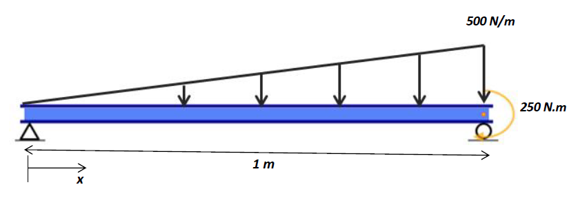
Transcribed Image Text:500 N/m
250 N.m
1 m
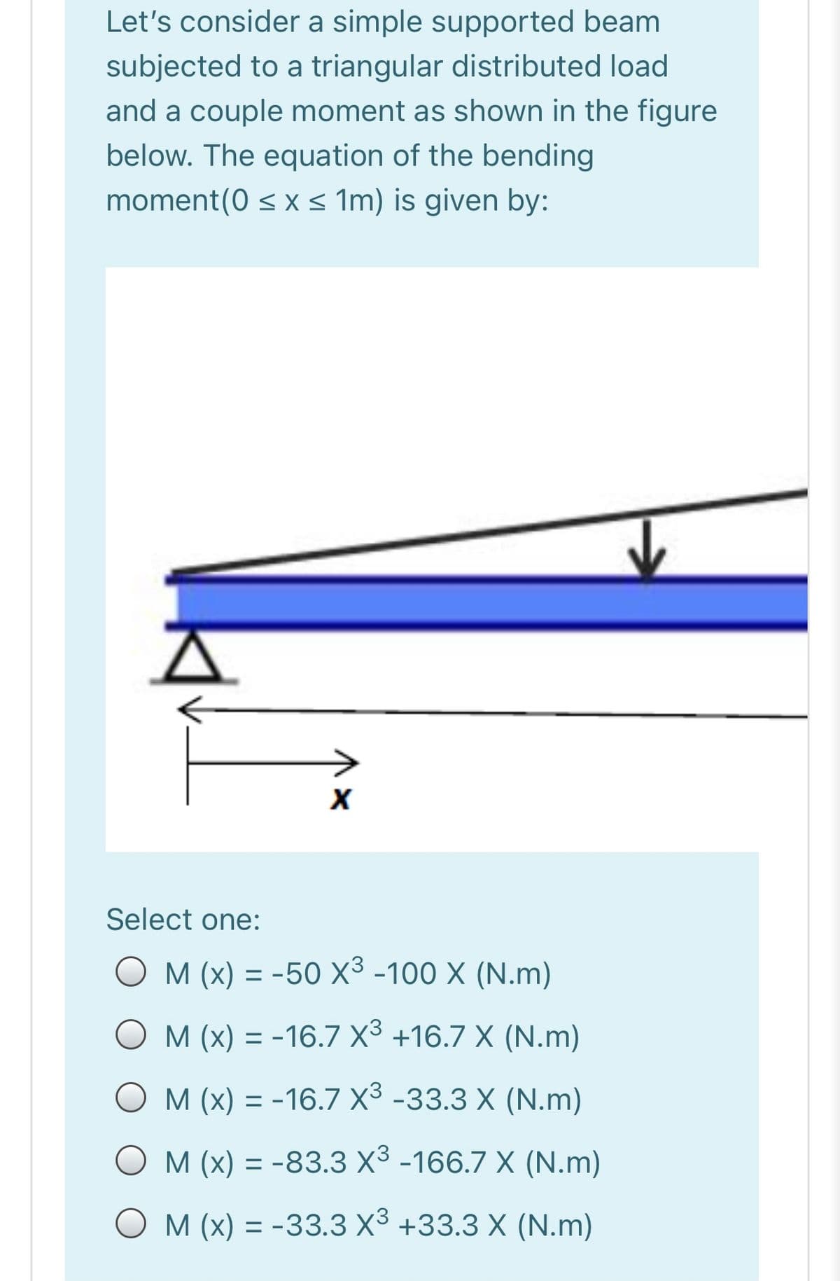
Transcribed Image Text:Let's consider a simple supported beam
subjected to a triangular distributed load
and a couple moment as shown in the figure
below. The equation of the bending
moment(0 < x < Im) is given by:
Select one:
M (x) = -50 X³ -100 X (N.m)
O M (x) = -16.7 X3 +16.7 X (N.m)
O M (x) = -16.7 X3 -33.3 X (N.m)
%3D
O M (x) = -83.3 X3 -166.7 X (N.m)
%3D
O M (x) = -33.3 X3 +33.3 X (N.m)
Expert Solution
This question has been solved!
Explore an expertly crafted, step-by-step solution for a thorough understanding of key concepts.

Step by step
Solved in 2 steps with 2 images

Knowledge Booster


Learn more about
Need a deep-dive on the concept behind this application? Look no further. Learn more about this topic, mechanical-engineering and related others by exploring similar questions and additional content below.Recommended textbooks for you
Mechanics of Materials (MindTap Course List)
Mechanical Engineering
ISBN:
9781337093347
Author:
Barry J. Goodno, James M. Gere
Publisher:
Cengage Learning
Mechanics of Materials (MindTap Course List)
Mechanical Engineering
ISBN:
9781337093347
Author:
Barry J. Goodno, James M. Gere
Publisher:
Cengage Learning