
Mechanics of Materials (MindTap Course List)
9th Edition
ISBN: 9781337093347
Author: Barry J. Goodno, James M. Gere
Publisher: Cengage Learning
expand_more
expand_more
format_list_bulleted
Videos
Textbook Question
Chapter 4, Problem 4.3.16P
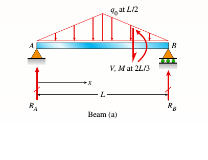
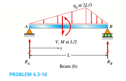
Find expressions for shear force V and moment Mat x = 2L/3 of beam (a) in terms of peak load intensity q0and beam length variable L. Repeat for beam (b) but at x = L/2.
Expert Solution & Answer
Want to see the full answer?
Check out a sample textbook solution
Students have asked these similar questions
An I-beam has a flange width b = 400 mm , height hℎ = 400 mm , web thickness tw = 13 mm , and flange thickness tf = 21 mm . Use the following steps to calculate the shear flow at the point shown, where x = 55 mm .
A) The formula for the shear flow includes the moment of inertia of the whole cross section, I, about the neutral axis. Calculate the moment of inertia.
B) The shear flow at the point depends on the value of Q for the portion of the upper flange to the right of the point. Calculate the value of Q
C) Use the results from Parts A and B to calculate the shear flow at the point in the upper flange 55 mm to the right of the web if the shear force on the section is V = 4.6 kN
An I-beam has a flange width b = 400 mm , height h = 400 mm , web thickness tw = 13 mm , and flange thickness tf = 21 mm . Use the following steps to calculate the shear flow at the point shown, where x = 55 mm .
A) The formula for the shear flow includes the moment of inertia of the whole cross section, I, about the neutral axis. Calculate the moment of inertia.
B) The shear flow at the point depends on the value of Q for the portion of the upper flange to the right of the point. Calculate the value of Q
C) Use the results from Parts A and B to calculate the shear flow at the point in the upper flange 55 mm to the right of the web if the shear force on the section is V = 4.6 kN
Uniformly distributed load on a simple support beam with a length of 6 metersMaximum that occurs on the cross section when q is appliedIf bending stress is 337.5MPa,How many kN/m is the equal distribution load q?(However, the cross section of the beam is wide x height = 40mm x)100 mm.)
Chapter 4 Solutions
Mechanics of Materials (MindTap Course List)
Ch. 4 - Calculate the shear force V and bending moment...Ch. 4 - Determine the shear force V and bending moment M...Ch. 4 - Determine the shear force V and bending moment M...Ch. 4 - Calculate the shear force V and bending moment M...Ch. 4 - Consider the beam with an overhang shown in the...Ch. 4 - The beam ABC shown in the figure is simply...Ch. 4 - The beam ABCD shown in the figure has overhangs at...Ch. 4 - At a full d raw, an archer applies a pull of 130 N...Ch. 4 - A curved bar ABC is subjected to loads in the form...Ch. 4 - Under cruising conditions, the distributed load...
Ch. 4 - A beam ABCD with a vertical arm CE is supported as...Ch. 4 - A simply supported beam AB supports a trapezoid...Ch. 4 - Beam ABCD represents a reinforced-concrete...Ch. 4 - Find shear (V) and moment (M) at x = 3L/4 for the...Ch. 4 - Find expressions for shear force V and moment M at...Ch. 4 - Find expressions for shear force V and moment Mat...Ch. 4 - Find expressions for shear force V and moment Mat...Ch. 4 - Find expressions for shear force V and moment M at...Ch. 4 - Find expressions for shear force V and moment M at...Ch. 4 - Find expressions for shear force V and moment M at...Ch. 4 - A cable with force P is attached to a frame at A...Ch. 4 - Find expressions for shear force V and moment M at...Ch. 4 - A cable with force P is attached to a frame at D...Ch. 4 - Frame ABCD carries two concentrated loads (2P at T...Ch. 4 - Frame ABC has a moment release just left of joint...Ch. 4 - The simply supported beam ABCD is loaded by a...Ch. 4 - The centrifuge shown in the figure rotates in a...Ch. 4 - Draw the shear-Force and bending-moment diagrams...Ch. 4 - A simple beam AB is subjected to a counter...Ch. 4 - Draw the shear-force and bending-moment diagrams...Ch. 4 - The cantilever beam AB shown in the figure is...Ch. 4 - Cantilever beam AB carries an upward uniform load...Ch. 4 - The simple beam AB shown in the figure is...Ch. 4 - A simple beam AB subjected to couples M1and 3M2...Ch. 4 - A simply supported beam ABC is loaded by a...Ch. 4 - A simply supported beam ABC is loaded at the end...Ch. 4 - A beam ABC is simply supported at A and B and has...Ch. 4 - Beam ABCD is simply supported at B and C and has...Ch. 4 - Draw the shear-force and bending-moment diagrams...Ch. 4 - The simple beam AB supports a triangular load of...Ch. 4 - The beam AB shown in the figure supports a uniform...Ch. 4 - A cantilever beam AB supports a couple and a...Ch. 4 - The cantilever beam A B shown in the figure is...Ch. 4 - Beam ABC has simple supports at .A and B. an...Ch. 4 - Beam ABC with an overhang at one end supports a...Ch. 4 - Consider the two beams shown in the figures. Which...Ch. 4 - The three beams in the figure have the same...Ch. 4 - The beam ABC shown in the figure is simply...Ch. 4 - A simple beam AB is loaded by two segments of...Ch. 4 - Two beams (see figure) are loaded the same and...Ch. 4 - The beam A BCD shown in the figure has overhangs...Ch. 4 - A beam ABCD with a vertical arm CE is supported as...Ch. 4 - Beams ABC and CD are supported at A,C, and D and...Ch. 4 - The simple beam ACE shown in the figure is...Ch. 4 - A beam with simple supports is subjected to a...Ch. 4 - A beam of length L is designed to support a...Ch. 4 - The compound beam ABCDE shown in the figure...Ch. 4 - Draw the shear-force and bending-moment diagrams...Ch. 4 - The shear-force diagram for a simple beam is shown...Ch. 4 - The shear-force diagram for a beam is shown in the...Ch. 4 - A compound beam (see figure) has an internal...Ch. 4 - A compound beam (see figure) has an shear release...Ch. 4 - A simple beam AB supports two connected wheel...Ch. 4 - The inclined beam represents a ladder with the...Ch. 4 - Beam ABC is supported by a tie rod CD as shown....Ch. 4 - A plane frame (see figure) consists of column AB...Ch. 4 - The plane frame shown in the figure is part of an...
Knowledge Booster


Learn more about
Need a deep-dive on the concept behind this application? Look no further. Learn more about this topic, mechanical-engineering and related others by exploring similar questions and additional content below.Similar questions
- Find expressions for shear force V and moment Mat x = 2L/3 of beam (a) in terms of peak load intensity q0 and beam length variable L. Repeat for beam (b).arrow_forwardA fixed-end beam AB of a length L is subjected to a uniform load of intensity q acting over the middle region of the beam (sec figure). Obtain a formula for the fixed-end moments MAand MBin terms of the load q, the length L, and the length h of the loaded part of the beam. Plot a graph of the fixed-end moment MAversus the length b of the loaded part of the beam. For convenience, plot the graph in the following nondimensional form: MAqL2/l2versusbL with the ratio b/L varying between its extreme values of 0 and 1. (c) For the special case in which ù = h = L/3, draw the shear-force and bending-moment diagrams for the beam, labeling all critical ordinates.arrow_forwardA simple beam AB of length L is subjected to loads that produce a symmetric deflection curve with maximum deflection S at the midpoint of the span (see figure). How much strain energy U is stored in the beam if the deflection curve is (a) a parabola and (b) a half wave of a sine curve?arrow_forward
- Find expressions for shear force V and moment M at mid-span of beam AB in terms of peak load intensity q0and beam length variables a and L Let a = 5L/b.arrow_forwardThe hollow box beam shown in the figure is subjected to a bending moment M of such magnitude that the flanges yield but the webs remain linearly elastic. (a) Calculate the magnitude of the moment M if the dimensions of the cross section are A = 15 in., A] = 12.75 in., h = 9 in., and ey =7.5 in. Also, the yield stress is eY = 33 ksi. (b) What percent of the moment M is produced by the elastic core?arrow_forwardA beam segment subjected to internal bending moments at sections A and B is shown along with a sketch of the cross-sectional dimensions. The beam segment is subjected to internal bending moments of MA = 1390 N·m and MB = 3080 N·m. The segment length is Δx = 180 mm. Consider area (2) and use cross-sectional dimensions of b = 92 mm, d = 240 mm, and d2 = 68 mm. (a) sketch a side view of the beam segment and plot the distribution of bending stresses acting at sections A and B. Indicate the magnitudes of key bending stresses on the sketch, including the stresses at the top and bottom of area (2) on both sections A and B. Tensile stresses are positive, while compressive stresses are negative. (b) determine the resultant forces acting in the x direction on the specified area at sections A and B, and show these resultant forces on the sketch. Tensile forces are positive, while compressive forces are negative. (c) determine the magnitude of the horizontal force required to satisfy equilibrium…arrow_forward
- A beam subjected to a bending test has internal vertical shear force V=2000N. The cross-sectional area is shown in the figure. What is the maximal shear stress? (Hint: the area moment (Q) is given by bh2/8, and the area moment of inertia of the cross-sectional area is equal to bh3/12, b is the width, h is the height).arrow_forwardA rectangular bar having width twice the depth is used as a beam. The beam is made of mild steel material having elastic modulus of 2.1 x 10⁵ N/mm? and it undergoes bending by external load which makes radius of curvature of 150 m. If the allowable bending stress in the beam is to be limited to 100 MN/m. find the cross section of the beam.arrow_forwardCalculate the maximum def lection δmaxof a uniformly loaded simple beam if the spanlength L = 2.0 m, the intensity of the uniform loadq =2.0 kN/m, and the maximum bending stressσ = 60 MPa.The cross section of the beam is square, and thematerial is aluminum having modulus of elasticityE = 70 GPa.arrow_forward
- A cantilever beam of cross section 90 mm.width 120mm deep Carrie's a UDL of 12KN/m. Over the entire length and a concentrated load of 15 KN at right end. find the bending stress in the beam, when the length of beam is 10 m.arrow_forwardProblem 4 For the beam shown below, find the value of EIY at 2m from R2. E= 18500MPa and; beam cross -section=200mmX275mm . Use Area-moment method w=15kN/marrow_forwardBeam ABCD represents a reinforcedconcretefoundation beam that supports a uniformload of intensity q1 = 3500 lb/ft (see figure). Assumethat the soil pressure on the underside of the beam isuniformly distributed with intensity q2.(a) Find the shear force VB and bending momentMB at point B.(b) Find the shear force Vm and bending momentMm at the midpoint of the beam.arrow_forward
arrow_back_ios
SEE MORE QUESTIONS
arrow_forward_ios
Recommended textbooks for you
 Mechanics of Materials (MindTap Course List)Mechanical EngineeringISBN:9781337093347Author:Barry J. Goodno, James M. GerePublisher:Cengage Learning
Mechanics of Materials (MindTap Course List)
Mechanical Engineering
ISBN:9781337093347
Author:Barry J. Goodno, James M. Gere
Publisher:Cengage Learning
Mechanical SPRING DESIGN Strategy and Restrictions in Under 15 Minutes!; Author: Less Boring Lectures;https://www.youtube.com/watch?v=dsWQrzfQt3s;License: Standard Youtube License