points A, B and D, respectively, as shown in the figure. A uniformly distributed loac of 4 kN/m acting vertically downwards extends for a length of 4 m between point A and C. Page 3 of 6 5 kN 10 kN 4 kN/m A 2 m 2 m 1 m 2 m 30 kN Figure Q2: A cantilever beam 2.1. Calculate the magnitudes and directions of the support reaction force RE and bending moment ME and at point E. 2.2. Establish the equations of shear forces (SF) and bending moments (BM) for each span of the beam. 2.3. On the basis of the established equations for SF and BM for the cantilever beam, construct the shear force and bending moment diagrams along the entire span of the beam. 2.4. Determine the magnitude and position of the maximum bending moment acting on the beam. 2.5. Calculate and show the positions of the points of contra-flexure (PCE)
points A, B and D, respectively, as shown in the figure. A uniformly distributed loac of 4 kN/m acting vertically downwards extends for a length of 4 m between point A and C. Page 3 of 6 5 kN 10 kN 4 kN/m A 2 m 2 m 1 m 2 m 30 kN Figure Q2: A cantilever beam 2.1. Calculate the magnitudes and directions of the support reaction force RE and bending moment ME and at point E. 2.2. Establish the equations of shear forces (SF) and bending moments (BM) for each span of the beam. 2.3. On the basis of the established equations for SF and BM for the cantilever beam, construct the shear force and bending moment diagrams along the entire span of the beam. 2.4. Determine the magnitude and position of the maximum bending moment acting on the beam. 2.5. Calculate and show the positions of the points of contra-flexure (PCE)

Mechanics of Materials (MindTap Course List)
9th Edition
ISBN:9781337093347
Author:Barry J. Goodno, James M. Gere
Publisher:Barry J. Goodno, James M. Gere
Chapter4: Shear Forces And Bending Moments
Section: Chapter Questions
Problem 4.5.27P: The simple beam ACE shown in the figure is subjected to a triangular load of maximum intensity q0=...

Related questions
Question
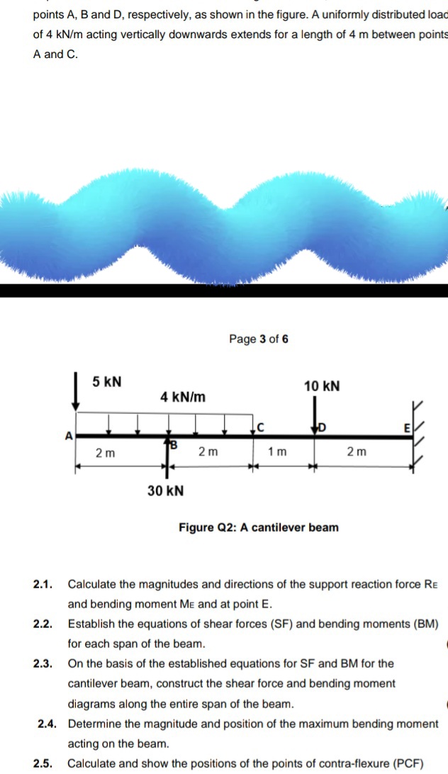
Transcribed Image Text:points A, B and D, respectively, as shown in the figure. A uniformly distributed loac
of 4 kN/m acting vertically downwards extends for a length of 4 m between point
A and C.
Page 3 of 6
5 kN
10 kN
4 kN/m
A
2 m
2 m
1 m
2 m
30 kN
Figure Q2: A cantilever beam
2.1.
Calculate the magnitudes and directions of the support reaction force RE
and bending moment ME and at point E.
2.2.
Establish the equations of shear forces (SF) and bending moments (BM)
for each span of the beam.
2.3.
On the basis of the established equations for SF and BM for the
cantilever beam, construct the shear force and bending moment
diagrams along the entire span of the beam.
2.4. Determine the magnitude and position of the maximum bending moment
acting on the beam.
2.5.
Calculate and show the positions of the points of contra-flexure (PCE)
Expert Solution
This question has been solved!
Explore an expertly crafted, step-by-step solution for a thorough understanding of key concepts.

Step by step
Solved in 6 steps with 7 images

Knowledge Booster


Learn more about
Need a deep-dive on the concept behind this application? Look no further. Learn more about this topic, mechanical-engineering and related others by exploring similar questions and additional content below.Recommended textbooks for you
Mechanics of Materials (MindTap Course List)
Mechanical Engineering
ISBN:
9781337093347
Author:
Barry J. Goodno, James M. Gere
Publisher:
Cengage Learning
Mechanics of Materials (MindTap Course List)
Mechanical Engineering
ISBN:
9781337093347
Author:
Barry J. Goodno, James M. Gere
Publisher:
Cengage Learning