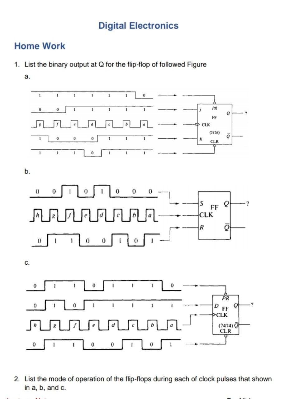
List the binary output at Q for the flip-flop of followed Figure


Q: If LM = 00, the next state of the flip-flop is 1. If LM = 01, the next state of the flip-flop is the…
A: Flip-flops: Flip-flop is used as a storage device that stores 1 bit at a time. This is used in…
Q: Design synchronous counter using JK flip flops to count the following binary numbers 0000 ,…
A: We have to design synchronous counter using JK flip flops to count the following binary number:…
Q: Design a counter to produce the following sequence. Use J-K flip-flops. 0, 2, 1, 3, 0, .
A:
Q: Q1) Cosider a mod. 4 binary counter and an input x so that it counts the repeated sequence…
A: For MOD 4 when x = 1 sequence is 0-1-2-3-0 When x =0 sequence is 0-3-2-1-0 to count above…
Q: A pattern detector which gives 1 at its 1-bit output when the last four values of its 1-bit input…
A: We are authorized to answer three subparts at a time, since you have not mentioned which part you…
Q: 4- The following serial data are applied to the Flip - Flop below. Determine the resulting serial…
A:
Q: Verify the truth table of JK and Maste-Slaves flip flop using its logic gates.
A: Verify the truth table of JK and Master-Slaves flip flop using its logic gates.
Q: Find the binary assignment table for the following circuit, then re-design it using JK flip flops. S…
A: Given circuit diagram: To find: Binary assignment table for the following circuit and re-design it…
Q: Show how a synchronous BCD decade counter with J - K flip - flops can be implemented having a…
A:
Q: Question By using a S-R flip - flop design a binary counter with the following sequence 0, 1,3,2,6,…
A:
Q: Find the binary assignment table for the following circuit, then re-design it using JK flip flops. R…
A: The binary assignment table shows the present state, next state and output. The present state, if…
Q: Find the binary assignment table for the following circuit, then re-design it using JK flip flops.
A:
Q: Consider the following Edge Triggered D Type Flip-Flop with Set (S), Reset (R) and the D inputs
A: The solution can be achieved as follows.
Q: þesign a 3-bit synchronous binary counter using JK flip-flop and draw the logic diagram of a 3-bit…
A: Given: A 3-bit synchronous binary counter using JK flip-flop having state table in the form: To…
Q: For the input waveforms in figure below, determine the Q output if: 1) The J-K flip-flop is negative…
A:
Q: HW : Plot the output waveform (Q) for T Flip-Flop : Clk Pre
A: To plot the waveform of Q of the negative edge trigger T Flip-flop is drawn with the help of the…
Q: Q2: Simplify A PN flip -flop has four operations. clear to zero. no change. complement. and set to…
A: Consider the given data: Here, PN flip-flop operations are, “Clear to 0” for the inputs PN=00 “No…
Q: Demonstrate how JK flip-flop can be converted into a D flip-flop. Also, represent the characteristic…
A:
Q: For a master-slave J - K Flip - Flop with the inputs below, sketch the Q output waveform. Assume Q…
A: Note: As per company guidelines, only the first question will be solved. If any other solution is…
Q: Design a counter which simultaneously satisfies all of the following requirements: • Have no input •…
A: We need to design a counter circuit for the given state diagram :…
Q: Determine the output states for this J-K flip-flop, given the pulse inputs shown:
A: JK flip flop truth table
Q: Figure shows the function table of a certain flip-flop. Identify the flip-flop. K Qn+1 Qnt1 Pr CI…
A: From the given below truth table we need to identify the type of option it suits for. Lets go…
Q: Determine the Q output for the J-K flip-flop, given .2 +ha innuts shown. CLK CLK K
A: The digital circuits can be combinational as well as sequential circuits. The combinational circuits…
Q: Find the binary assignment table for the following circuit, then re-design it using JK flip flops.…
A: For the given logical circuit, binary assignment table is drawn, which shows that Output is set only…
Q: A counter need to produce the following binary sequence using JK flip flops 1,4,3,5,7,6,2,1 Draw the…
A:
Q: Design a three bit counter which counts in the following sequence: 001, 010, 101, 110, 111, 011,…
A: Draw the state diagram table for the JK flip-flop. Present State Next State Inputs Q(t)…
Q: Q2\Design a counter to produce the following binary sequence. Use J-K flip-flops.…
A: Design a counter to produce the following binary sequence, Use J-K flip flops…
Q: Verify the truth table of JK and Maste-slaves flip flop with its logic gates
A: Verify the truth table of JK and Master-slaves flip flop with its logic gates
Q: triggered flip-flop) for: (a) T flip-flop with active low clear (CLR') and preset (PRE') (b) T…
A:
Q: D Q X D CLK
A:
Q: By giving the truth table of the SR Triggered Flip Flop, determine how the Q and Q' outputs will…
A:
Q: JK Flip-flops J Example Determine the Q output for the J-K flip-flop, assuming Q is initially high.…
A:
Q: Using T flip flops, Implement a 3-bit asynchronous binary counter.
A:
Q: 5. If the flip-flop is set, what are the output states of the master and slave when a high is…
A: The given circuit diagram is
Q: Q2: If a 10-bit ring counter has the initial state as shown in figure below, determine the counter…
A: The given 10-bit ring counter is Here, the ring counter is a right-shift register with input as…
Q: Using a D flip-flop and a minimum number of additional logic gates, design each of the flip-flops…
A: The following table shows the state table of D flip-flop. D Qt 0 0 1 1
Q: 1. For a master-slave J - K Flip - Flop with the inputs below, sketch the Q output waveform. Assume…
A: Flip flop is a latch with additional control input (clock or enable ). A flip flop is used to store…
Q: verify the truth tables of JK and Maste-slaves flip flop with its logic gate
A:
Q: Create a 5-bit shift right register using D flip-flops. Given an initial value of Din=1 and Q4 Q3 Q2…
A:
Q: Design a counter to produce the following binary sequence. Use J-K flip-flops. 0, 9, 1, 8, 2, 7, 3,…
A: Given: The binary sequence given is, The counter is need to be designed to produce the above…
Q: By giving the truth table of the JK Flip Flop, determine how the Q and Q outputs will take value in…
A: By giving the truth table of the JK Flip Flop, determine how the Q and Q outputs will take value in…
Q: Design a counter to produce the following binary sequence. Use J-K flip-flops. 0,9, 1, 8, 2, 7, 3,…
A: counting sequence is 0,9,1,8,2,7,3,6,4,5,0 repeats..
Q: Find the binary assignment table for the following circuit, then re-design it using JK flip flops. S…
A: For the given logical circuit, binary assignment table is drawn, which shows that Output is set only…
Q: Q.5 Design a synchronous counter that will count according to the following sequence: 0-1-3-7 and…
A:
Q: Given the clock, preset and clear inputs of the D flip-flop below, draw the timing diagram of the Q…
A:
Q: Design a binary counter with the following repeated binary sequence: Use JK-type Flip-Flops. 0, 1,…
A: Counting Sequence is 0-1-2-3-4-5-6-7-0 repeats on This binary counter is also known as MOD-8…
Q: By giving the truth table of the SR Triggered Flip Flop, determine how the Q and Q outputs will take…
A:
Q: H.W Q/ Show how a synchronous BCD decade counter with J-K flip-flops can be implemented having a…
A:
Q: 1) For the given waveforms determine the output Q and name the reasons for it. Assume that the Flip-…
A: The given waveform is:

Step by step
Solved in 2 steps


- Define the following: flip-flops state table state diagram excitation table characteristic table characteristic equation state reductionJK Flip Flop State Machine Create Logic Diagram based on Design Equations J1 = K1 = Q0 A’ , J0 = A , K0 = A’ , Y = Q0 , X = Q1 Q0’Assume Flip flop is initially set to 01(Q1Q0) in the given counter circuit. Accordingly, determine the outputs of the counter given after each clock pulse.
- Implementation of 8-bit Floating Light Digital Circuit Using JK Flip-Flopdesign it. (Hint: Using Shift Register)2. Draw a ripple decade counter using negative edge-triggered JK flip-flops and draw the timing diagram.a. ABCD=1010, Write the value of the shift register after applying three clock pulse. (D-flip flop)b. Complete the following timing diagram for a T flip-flop. Assume no gate delay
- Compare the circuits, characteristic tables, and the timing diagrams of SR Flip-flops, JK flip-flops, and D flip flops. In your own words, describe the similarity and differences in behavior of these flip flops. Then go on to make comparison between Mealy and Moore machines, first describe each FSM and then elaborate on the similarity and differences between them.Design a 2-bit synchronous binary counter using T flip-flops. Requirements: a.) State diagram b.) state table c.) State equation : A (t+1) = B (t+1) = d.) Flip-flop input functions : e.) Logic diagramDesign a 3 bits binary synchronous counter with JK flip-flops. That count the odd numbers