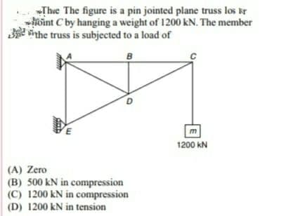
Thue The figure is a pin jointed plane truss los kr int C by hanging a weight of 1200 kN. The member 3e vinhe truss is subjected to a load of B m 1200 KN (A) Zero (B) 500 kN in compression (C) 1200 kN in compression (D) 1200 kN in tension
Q: Q 3: In Fig. 2, Find the Force in members DC, EC, EF Using Method of Sections and in Members AE & BG…
A:
Q: The cantilever truss in the figure is hinged at D and E. Find the force in member CE.
A:
Q: PROBLEM SP306 200 KN For the truss subjected by parallel forces as shown, determune the reaction at…
A:
Q: The roof truss shown in the figure is supported at A and B carries a vertical loads at each of the…
A:
Q: Illustrative Problem: For the truss loaded as shown in the figure, determine; a. the magnitude and…
A:
Q: tresses are 140 MPa in tension and 100 MPa in compression. H 4.5 m B E- 120 kN 150 kN 60 kN 4 panels…
A: To find area if member CH
Q: Consider the truss shown in the figure below. Determine the force in the member AD and CD. (indicate…
A:
Q: 1- For the truss shown in below, find the internal fore in member BE, and DG. MATHalino.com 1.5 m 2m…
A: GIVEN DATA- A PLANE TRUSS GIVEN WE HAVE TO FIND FORCE IN MEMBER BE AND DG
Q: Solve the following problems by the method of sections. State whether the members are in tension or…
A:
Q: The light boom AB is attached to a vertical wall by a ball and socket joint at A and supported by…
A:
Q: The frame illustrated above supports a load P= 4.70 kN. The frame dimesions are 3,400 mm, a = 1,200…
A: Draw the free body diagram for the above problem.
Q: Solve the following problems by the method of sections. State whether the members are in tension or…
A: Drawing the FBD of the entire truss:
Q: In the figure, L = 3.0 m and P = 590 kN. Compute the member forces listed below. In each case,…
A:
Q: 800 lbs 500 lbs 8 ft 5. B 3 8 ft A E 6 ft For the simple plane (2D) truss shown in the figure,…
A:
Q: Determine the force in members DF, FG, and Gl of the triangular Howe truss shown in figure below.…
A:
Q: D F 4m E 3m 3m he pin-jointed frame work in the figure If a vertical concentrated load of 800KN…
A:
Q: For the truss in the figure below, if P = 7 kN, what is the force in member DC? -3 m-3 m-3 m- F E VP…
A: Given data P=7 kN
Q: Determine the force in members DF, FG, and Gl of the triangular Howe truss shown in figure below.…
A:
Q: The wooden pile shown in the figure has a diameter of 105 mm and is subjected to a load of P = 70…
A:
Q: Determine the force in members DF, FG, and Gl of the triangular Howe truss shown in figure below.…
A:
Q: a) What is a truss? Explain shortly in your own words, and illustrate with one example. b) For the…
A: Answer (a): Truss: A fixed frame of members which is used to support something (roof, bridge) is…
Q: problem 1.3-9 solution plz....
A: Drawing the free body diagram of the truss as shown below –
Q: D{ C l 5) The box truss shown in the figure is loaded by three vertical forces acting at joints A,…
A:
Q: Determine the forces on the FG and GI bars of the truss shown in the figure. Consider the load P =…
A:
Q: a) What is a truss? Explain shortly in your own words, and illustrate with one example. b) For the…
A:
Q: All the tension/compression members of the frame structure shown in the figure are pin-jointed and…
A:
Q: Specily where th (c) Find the support reactions at A and C (As shown in the figure, A is a pin…
A:
Q: 8. What is the force in member AB of the truss, as shown in the Figure, with P1 = 2 kN and P2 = 2…
A:
Q: Determine the force in members DF, FG, and Gl of the triangular Howe truss shown in figure below.…
A:
Q: The truss shown in the figure is pin supported at A and witha roller at G. Determine the magnitude…
A:
Q: A frame shown in the figure below is supported by a hinge at E and a roller at D. Compute the…
A:
Q: Solve the following problems by the method of sections. State whether the members are in tension or…
A: Given: length of each truss member is l=5 ft and the forces on particular members are shown in the…
Q: The simple truss is loaded by a system of forces as shown in the figure. The truss is supported by a…
A:
Q: Solve the following problems by the method of sections. State whether the members are in tension or…
A: To find The forces in the member DE, EJ, and JH. FBD: The free body diagram is shown below. Given…
Q: B D F 3. A Howe truss is loaded as shown below, P = 32 kN. a) Find the support reactions at A and Н.…
A:
Q: A truss is composed of members AB, BC, CD, AD and BD, as shown in the figure. A vertical load of 10…
A: Consider the free-body diagram as shown below.
Q: Q.1) For the following space truss where F1 = {300i + 400j -500k}, F2 = {600j}: (a) Find the force…
A:
Q: BI,Cf, fg Q.2) For the truss shown in figure below, determine the forces in Tole
A:
Q: Considering the structure shown in the following figure: e the internal forces on each member of the…
A:
Q: The simple truss is loaded by a system of forces as shown in the figure. The truss is supported by a…
A: Given data: The magnitude of the force P acting on the truss is P = 800 lb.
Q: Example 4 Determine reaction and the force in all members by joint method as shown in truss? Find…
A:
Q: See the truss shown below, supported by pins at A and G. Determine the force in members BC, CF, and…
A:
Q: -1.5 m 10 kN- 1 m E 1 m D. 3D 1 m A B
A:
Q: From the figure, the load at G is 12 kN: To determine: a) Piston force JL b) Pin force E and M c)…
A: Draw FBD of GEM and calculate pin forces at E and M:
Q: 2. A 12- ft. bar of negligible weight rests in a horizontal position on the smooth inclines in…
A:
Q: Problem 3: Given: Truss ABCDE below. P1 = 6 kN P2 = 8.6 kN Find: The magnitude of the force in each…
A:
Q: 2P 2P 2P * [m] Calculate the support reactions and the bar forces of the truss! P = 19.00 kN a =…
A:
Q: giew. given in the figure below, is (A) 27 kN (Tensile) (B) 15 kN (Compressive) C) 20 kN…
A:
Q: Consider the simply supported truss as defined in the figure and parameter table. Find the force in…
A:
Q: a) Find the forces in the members AE, AC, BE, and BD of the given frame in Fig.2 and indicate…
A:
Step by step
Solved in 2 steps with 2 images
- A soccer goal is subjected to gravity loads (in the - z direction, w = 73 N/m for DG, BG, and BC; w = 29 N/m for all other members; see figure) and a force F = 200 N applied eccentrically at the mid-height of member DG. Find reactions at sup ports C, D, and H.A truss ABC supports a load W at joint B, as shown in the figure. The length L, of member Aß is fixed, but the length of strut BC varies as the angle is changed. Strut BC has a solid circular cross section. Joint B is restrained against displacement perpendicular to the plane of the truss. Assuming that collapse occurs by Etiler buckling of the strut determine the angle for minimum weight of the strut.A cylindrical brick chimney of height H weighs w = 825 lb/ft of height (see figure). The inner and outer diameters are d1= 3 ft and d2= 4 ft, respectively. The wind pressure against the side of the chimney is p = 10 lb/ft2 of projected area. Determine the maximum height H if there is to be no tension in the brickwork.
- The roof over a concourse at an airport is supported by the use of pretensioned cables. At a typical joint in the roof structure, a strut AB is compressed by the action of tensile forces Fin a cable that makes an angle = 75° with the strut (see figure and photo). The strut is a circular tube of steel (E = 30,000 ksi) with outer diameter d2= 2.5 in. and inner diameter d1= 2.0 in. The strut is 5.75 ft long and is assumed to be pin-connected at both ends. Using a factor of safety n = 2.5 with respect to the critical load, determine the allowable force F in the cable.Continuous cable A DB runs over a small friction less pulley al D to support beam OABC, which is part of an entrance canopy for a building (see figure}. The canopy segment has a weight W = 1700 lb that acts as a concentrated load in the middle of segment AB. (a) What is the maximum permissible value of load P at C if the allowable force in the cable is 4200 lb? (b) If P = 2300 lb, what is the required diameter of pins A, B, and D? Assume that the pins are in double shear and the allowable shear stress in the pins is 10 ksi.A steel post (E=30×106) having thickness t = 1/8 in. and height L = 72 in. support a stop sign (see figure), where s = 12.5 in. The height of the post L is measured from the base to the centroid of the sign. The stop sign is subjected to wind pressure p = 20 lb/ft2 normal to its surface. Assume that the post is fixed at its base. What is the resultant load on the sign? (Sec Appendix E, Case 25, for properties of an octagon, n =8.) What is the maximum bending stress in the post? Repeat part (b) if the circular cut-outs arc eliminated over the height of the post.
- The plane truss shown in the figure supports vertical loads F at joint D, 2F at joint C, and 3F at joint B. Each member is a slender circular pipe (E = 70 GPa) with an outside diameter of 60 mm and wall thickness of 5 mm. Joint B is restrained against displacement perpendicular to the plane of the truss. Determine the critical value of load variable F(kN) at which member BF fails by Eu1er buckling.A plane truss has a pin support at F and a roller support at D (see figure). (a) Find reactions at both supports (b) Find the axial force in truss member FE.The truss ABC shown in the figure supports a vertical load W at joint B. Each member is a slender circular steel pipe (E = 30,000 ksi) with an outside diameter of 4 in. and wall thickness 0.25 in. The distance between supports is 23 ft. Joint B is restrained against displacement perpendicular to the plane of the truss. Determine the critical value Wcr of the load.
- A crane boom of mass 450 leg with its center of mass at C is stabilized by two cables AQ and BQ (Ae= 304 mm2 for each cable) as shown in the figure. A load P = 20 KN is supported at point D. The crane boom lies in the y-z plane. (a) Find the tension forces in each cable: TAQand TBQ(kN}. Neglect the mass of the cables, but include the mass of the boom in addition to load P. (b) Find the average stress (s) in each cable.Determine the forces on the FG and GI bars of the truss shown in the figure. Consider the load P = 36 KN.in the fink truss shown in fig. p-4-4.5, the web members BC and EF are perpendicular to the inclined members of their midpoints. if p=2000lb, use the method of sections to determine the force in DF, DE, and CE