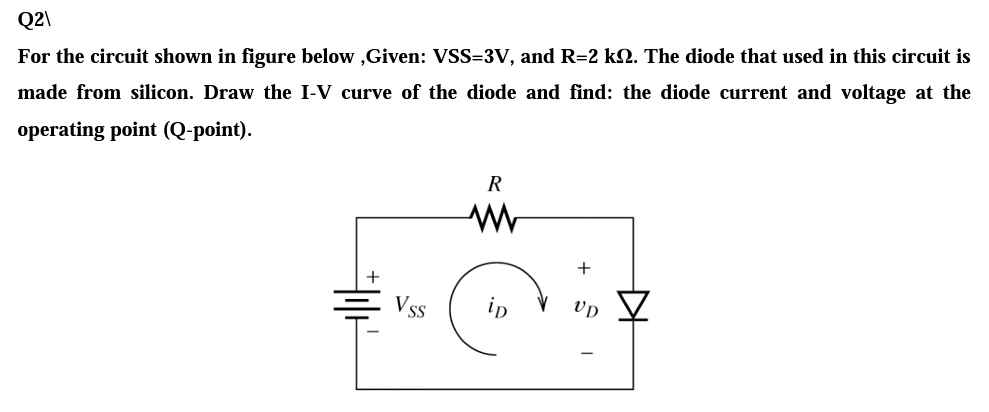
nade from silicon. Draw the I-V curve of the diode and find: the diode current and voltage at the perating point (Q-point). R Vss ip vp


Q: The zener diode in the voltage-regulator circuit given below has a breakdown voltage of 9V. Suppose…
A:
Q: For the given circuit below, compute for the diode current. Si RL 8 k2 Vs 18 V-
A: In this question we will find current I..
Q: For the circuit shown in figure, the diode current is given by / = lo(evr - 1) where V, equal to 25…
A:
Q: In the given i-v characteristic below, which load line represent the given circuit? I-V curve for a…
A: We need to find out load line for given circuit
Q: 15 In the circuit shown, determine the current flowing through the resistor R1. * R2 1K R1 5V D2 1K
A: The solution is given below
Q: A pn diode has a resistivity of 1 Ω·cm on the p-type side and 0.02 Ω·cm on the n-type side. What is…
A: Given data; Resistivity for p-side = 1 Ω·cm Resistivity for n-side = 0.02 Ω·cm Cross sectional area…
Q: Consider the diode to turn on "hard" at Vp-0.7 for any current i,2 OmA. Sketch the transfer…
A: For the given circuit we have to sketch the input verse output graph Given the diode cutin voltage…
Q: The zener diode in the voltage-regulator circuit given below has a breakdown voltage of 9V. Suppose…
A: In the circuit, find the voltage Vs range if the reverse current range of the zener diode is given.
Q: or the diode circuit shown, all diodes are identical with Is = 10-14 A. ind the value of the current…
A: Given: IS=10-14A and V0=2 V The current through the diodes is required
Q: ( Figure B.1 shows a diode circuit and its DC load line analysis. Based on the information obtained…
A:
Q: (a) Find the worst-case values of the Q-point current for the diode shown using the ideal diode…
A: (a) Draw the circuit, when the diode is forward biased, and the resistors with the added values of…
Q: A diode has 1 mA at 0.6 V and 120 mA at 0.8 V. Find a piecewise model (battery+resistor) for that…
A: Given: A diode has 1 mA at 0.6 V and 120 mA at 0.8 V. To find: The piecewise (battery+resistance)…
Q: + VD - LD R1 R3 V2 V1 (10 points) V3 ER2 In the circuit above, given V = 6V, V2 = 4V, V3 = 1v, R =…
A:
Q: In the circuit shown, determine the current flowing through the resistor R1. (Use 2nd approximation…
A:
Q: tion-2: For the circuit shown below at témperature 35°: hich diode will operate first? Why?…
A: As per Bartleby guidelines we are allowed to solve only three subparts, please ask the rest again.
Q: A breakdown diode has iD=−10−6(1+vD/5)3 for −5 V<vD<0 where iD is in amperes. Plot iD versus…
A: The plot for iD vs vD is drawn below:
Q: (a) A diode used in the Figure Q2 (a), has a characteristic as shown by the I-V graph. Obtain the…
A: Applying KVL in the given circuit 25ID=2.5-VDID=2.525-VD2.5ID=-VD2.5+110 Compare it with equation of…
Q: With the given circuit below, if the input voltage is 10 volts peak-to-peak and the diode is…
A: The diode is ON when the voltage across anode is more than the cathode voltage. It is known as…
Q: Minority carrier distribution of a silicon p-n junction is given below for zero- bias. Find the…
A: Given, Volume = 2 × 10-12 cm3 Minority charge carrier of n = 105
Q: Find the current through the diode in the circuit shown. Assume the diode to be ideal. 50 92 R₁ D V…
A:
Q: A diode has a doping of ND = 1015/cm3 on the n-type side and NA = 1017/cm3 on the p-type side. What…
A: The built-in potential of the given diode is given by the expression as shown below: Plugging the…
Q: A FWBR with an RL load is connected to a 120 V source. If the load resistance is 10 22 and L » R,…
A:
Q: A germanium diode is connected to a load resistance of 1.5 kQ and is supplied with 12-V such that…
A:
Q: Find the Total Current of the Circuit during the negative half cycle in milliamps. Consider the…
A:
Q: 3. For the given circuits in below, a) Find the values of Vin, VD and ID for the cases where the…
A: Given a diode circuit with two different cases diode is ideal andS Silisium(VT = 0,7V). Frequency…
Q: For an ideal diode which of the following is true? a) It allows the passage of current in the…
A: In the following sections, among the given statements, which are true for an ideal diode will be…
Q: For the diode circuits shown below, find the values of I1, I2 and V indicated. a) Using the…
A:
Q: MjA4MjoxOTAyNDI1/t/all Ex: Determine the dc resistance levels for the diode in Figure below at a.…
A: We know resistance is the ratio of voltage and current.
Q: B. For the circuit shown, determine and sketch the output voltages (Vo). (All diodes are Silicon…
A:
Q: Find the Voltage V2 of the Circuit below. Consider all of the Diodes as Silicon. Find the PIV of…
A: In the circuit, Find the Voltage V2 of the Circuit below. Consider all of the Diodes as Silicon.…
Q: Consider the circuit below containing two identical, p-n junction diodes D₁ and D₂: 2 ks2 www 5 V-…
A: Given, Threshold voltage VT=0.7V Ambient temperature=300K Reverse saturation current= IS=5μA Here,…
Q: 3. In the circuit shown below, the knee current of the ideal Zener diode is 10 mA. To maintain 5 V…
A:
Q: Use Load-Line analysis to solve for the diode current and the diode voltage in the following…
A:
Q: A semiconductor diode having ideal forward and reverse characteristics is used in a half-wave recti-…
A: First draw the current wave form of the diode current. Using rms value integral calculate rms value…
Q: Solve for the diode current Ip and the voltage across the load R using the three diode model: below:…
A:
Q: for a silicon diode with I s= 2.5 µ A at 300 °K, find the forward voltage at a forward current
A:
Q: IRL RL In the circuit using a Zener diode above, given that V, = 10 V, R 3.7 KQ, R = 6.8 KQ, and the…
A: Given circuit: Vi=10 VR=3.7 kΩRL=6.8 kΩVZ=5 V
Q: Consider the diode circuit shown in the figure, where R, = R2 = 1 kN. R1 o V. Vs(t) Ip R2 VB /hen VB…
A:
Q: . Consider the diode circuit shown in the figure, where R1 = R2 = 1 kN. v. v.(t) When V3 = 4 V and…
A:
Q: In PN junction in series with a 100 ohms resistor, is forwarded biased. So that a current of 100 mA…
A: Circuit diagram is given as, In first case diode is forward bias replacing the diode as short…
Q: V2 V3 D1 D2 {I + 2 2 2 2 V1 AC 12 R1 1k
A:
Q: For the given circuit below, if the diode is ideal.compute for the voltage across the load…
A: We need to find out voltage across diode for given circuit
Q: In a certain silicon diode, it was found that the diode current is 15mA when the diode voltage is…
A:
Q: For the circuit shown , when the diode is off Vo(t) = v V for Vs(t) %3D V 12kN +. 4V v,(t) (+ 12kN…
A:
Q: Use Load-Line analysis to solve for the diode current and the diode voltage in the following…
A:
Q: 14. For the following circuit, assuming the diode is ideal, find the steady state values for Voutp…
A:
Q: A diode circuit is shown in the figure below with R=100, L=5mH and Vs=220V. If a load current of 10A…
A: A diode circuit is shown in the figure below with R=10 Omega. L-5mH and Vs = 220V . If a load…
Q: 18 If the voltage at the cathode of a diode is -1 V, and the anode is connected to the ground, then…
A:
Q: SOLVE (show the process) for the current at room temperature in a diode if the forward voltage is…
A:
Q: In a certain silicon diode, it was found that the diode current is 15mA when the diode voltage is…
A: Here, we have a Si diode at room temperature. The diode current, ID1=15 mA The diode voltage,…

Step by step
Solved in 2 steps with 2 images


- The temperature dependence of resistance is also quantified by the relation R2=R1[ 1+(T2T1) ] where R1 and R2 are the resistances at temperatures T1 and T2, respectively, and is known as the temperature coefficient of resistance. If a copper wire has a resistance of 55 at 20C, find the maximum permissible operating temperature of the wire if its resistance is to increase by at most 20. Take the temperature coefficient at 20C to be =0.00382.Derive the equation of i(t), vc(t), and the energy absorb by the resistor R of a diode circuit with RC load figure that is shown:Consider the circuit below,assuming the diode is ideal:1) When voltage source (Vin) provides a positive voltage, the diode isequivalent to ____________ circuit2) When voltage source (Vin) provides a negative voltage, the diode isequivalent to ____________ circuit3) Sketch the I-V characteristic of the ideal diode model on the chart below.
- The zener diode in the voltage-regulator circuit given below has a breakdown voltage of 9V. Suppose that the diode has a resistance of 100Ω in the breakdown state and diode is to operate with a reverse current between 10mA and 100mA. Find the range of VS for the case that R = 200Ω and RL = 600Ω.Q1: In this Zener diode regulator, the source voltage varies from 6 V to 14 V. Assume that the load current varies between 1 mA and 35 mA, and that the diode is an ideal 4 V Zener diode. What is the largest allowable resistance that will ensure the load voltage remains constant with variations in load current and source voltage? Please enter your answer to 3 significant figures. Q2: Given the circuit design for a Zener diode regulator in the Ques 1, what is the maximum power that will be dissipated by the Rs resistor? You are told that the source voltage Vs varies from 6 V to 11 V, the load current il varies between 2 mA and 45 mA, and the diode is an ideal 3 V Zener diode. You will need to recalculate the maximum allowable resistance Rs with your new values, as part of this question. Please enter your answer to 3 significant figures, and in Watts.For the ideal-diode clipper circuit given below, VS = 12.sinωt V. Determine the output voltage Vout and sketch this function. Remove the short circuit between points x and y, and replace it with a 2kΩ Resistor. Find the range of values of VS for; D1 and D2 are OFF D1 is ON and D2 is OFF D1 is OFF and D2 is ON Is it possible for both D1 and D2 to be ON?
- The above circuit is a simplified boost converter used to generate output voltages higher than the input voltage (5V in this case). The switch is closed for t<0 and opens at t=0. Assume an ideal diode. Determine the state of the diode and the expression for vo(t) and its sketch. Verify your assumption on the state of the diode.Given that the zener diode has a valaue of Vz = 35 V. Find the maximum current flowing through the zener diode. **Please show your correct and complete solution for this circuit problem. ASAP! Thank you!**In the circuit shown, determine the current flowing through the resistor R1. (Use 2nd approximation and assume all diodes are silicon for all the problems)
- Suppose we have a 10-V-peak sinusoidal voltage source. Draw the diagram of a circuit that clips off the part of the sinusoid above 5 V and below -4 V. The circuit should be composed of ideal diodes, dc voltage sources, and other components as needed. Be sure to label the terminals across which the clipped output waveform vo(t) appears.Design a voltage-regulator circuit to provide a constant voltage of 5 V to a load from a variable supply voltage. The load current varies from 0 to 100 mA, and the source voltage varies from 8 to 10 V. You may assume that ideal Zener diodes are available. Resistors of any value may be specified. Draw the circuit diagram of your regulator, and specify the value of each component. Also, find the worst case (maximum) power dissipated in each component in your regulator. Try to use good judgment in your design. Repeat Problem P9.29 if the supply voltage ranges from 6 to 10 V.Design a voltage-regulator circuit to provide a constant voltage of 5 V to a load from a variable supply voltage. The load current varies from 0 to 100 mA, and the source voltage varies from 8 to 10 V. You may assume that ideal Zener diodes are available. Resistors of any value may be specified. Draw the circuit diagram of your regulator, and specify the value of each component. Also, find the worst case (maximum) power dissipated in each component in your regulator. Try to use good judgment in your design.