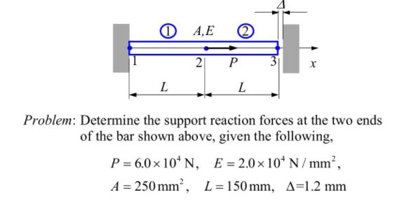
O 4,E 2 P L Problem: Determine the support reaction forces at the two ends of the bar shown above, given the following, P = 6.0× 10ʻ N, E=2.0×10* N / mm², A = 250 mm², L=150mm, A=1.2 mm %3D


Q: A uniform bar 3.00 m long is held by ropes at the ends making angle 60.0 and 30.0, respectively,…
A: Let us consider, Tension in rope of left end =T1 Tension in rope of right end = T2 Weight of bar =…
Q: 1 Three identical bars of lengths / are arranged and supported in a horizontal plane, as shown in…
A:
Q: The bent rod is supported by a thrust bearing at point A and a journal bearing at point D. The 100…
A:
Q: Problem #7: For the structure below find the maximum absolute vertical shear stress (Oxy) anywhere,…
A: Draw the above structure and mention the load location point as given below. Here RA signifies…
Q: P2) A brass bar, having cross-sectional area of 900 mm2, is subjected to axial force as shown below.…
A:
Q: Q3/ The below figure illustrates the cross section of a column and its bracing details for both its…
A:
Q: Consider the truss shown in (Figure 1). Suppose that F = 60 kN and F2 = 30 kN. !! Figure < 1 of 1 50…
A:
Q: Example 18. The homogeneous bar AB of 300 N is resting as shown in figure Ex.18. Assuming contact…
A:
Q: Shown in the following figure is a foldable table loaded by weight “W”. The contact points, B, D,…
A:
Q: The structure ABCD, is subjected to horizontal and vertical loads P and Q, Calculate the dis-…
A: Given: To find: Nodal displacements
Q: Determine the largest value of the load parameter P that can be applied to the trusses shown in Fig.…
A: Given: The elastic modulus, E = 200 GPa The cross-sectional area, A = 14.6 mm2 The moment of…
Q: The axially loaded bar ABCD shown in figure 2 is held between 2 rigid supports. The bar has…
A: The free-body diagram of the given axial bar can be drawn as below, Here, RA and RD are the…
Q: Q.14. A mass of 35kg is suspended from a weightless bar AB which is supported by a cable CB and a…
A: The free-body diagram of the system is given as,
Q: Q3: A rigid beam ABCD is supported as shown. Initially and at room temperature the beam is…
A: Given that ,
Q: A flanged wooden shape is used to support the loads shown on the beam. The dimensions of the shape…
A: Answer: (a) The maximum tension bending stress is 1530.2124 psi. (b) The maximum compression bending…
Q: A uniform steel bar of length 10 m is supported at point A and B using two cables as shown in the…
A:
Q: A F F W2 d A Section A-A The following figure shows the free-body diagram of a connecting-link…
A: FROM DATA BOOK, Sut=64kpsi Sy=54kpsi a=2.7 b=-0.265 kb=1 kc=0.85 endurance limit, Se=0.5Sut…
Q: (a) In Fig. a6.00-m-long, uniform beam is hangingfrom a point 1.00 m to the rightof its center. The…
A: Given Data: The weight of the beam is W1 = 140 N. The weight hanging at the top is W2 = 100 N. The…
Q: Consider the following showing the three-bar assembly. Nodes 1 and 4 are fixed. At node 2, a…
A: Draw the free-body diagrams of all three elements.
Q: Figure Y shows a rigid body consisting of beam ABC loaded with a 500 Nm moment, a box with a weight…
A: Given Data, Moment, M = 500 Nm(clockwise) Weight of the box,W = 600 N Mass of the tyre, m= 10 Kg To…
Q: A 15,000 N crane pivots around a friction-free axle at its base and is supported by a cable making a…
A: a.
Q: ka 2 ki P Rigid bar k3 for the system shown in the figure, which of the following statements are…
A: from the figure , we see that , point 1,2,3,4 are rigid on the wall , so they can't move while…
Q: Q4 (a) A thin eylinder 95 mm internal diameter, 500 mm long with walls 4.5 mm thick is subjected to…
A: The cylinder, as mentioned, is assumed as a thin shell. The internal pressure in a thin shell…
Q: The vertical reaction in the hinged support shown in the figure is Blank 1 N. 200 N 200 N B E 2 m 2…
A:
Q: In figure, if the floating ball radius is blä 5 0.5 m and its density= 2000 N/m3, the * ? cable…
A:
Q: A 10.7 m long beam is loaded as shown below and the hinge support is at x-2.4 distance from the left…
A:
Q: If the beam in the figure below is in equilibrium (A is a pin and B is a roller), determine the…
A:
Q: help me to understand that square or 90 degrees on 42 kn. how is that applied to get the solucion?…
A: Draw the section L-M which divide the truss into two parts such that it consists the members BC, CF…
Q: 3. A cylindrical rod is fixed between two walls. The rod is composed of two materials. Section AC is…
A:
Q: Example 4.2. A beam 3 m long weighing 400 N is suspended in a horizontal position by two vertical…
A: Given data: Length of the beam (L) = 3 m Weight of the beam = 400 N Weight of the body = 200 N Need…
Q: Q3: A rigid beam ABCD is supported as shown. Initially and at room temperature the beam is…
A:
Q: A cantilever solid pole 280 mm in diameter and 3m high weighs 22kN/m³. The pole is subjected to the…
A: Diameter of pole, d=280 mm Height of pole, h=3 m Weight of pole, w=22 kN/m3 Vertical load, P=3 kN…
Q: In the figure, the horizontal rigid beam ABCD is supported by vertical bars (1) and (2) and is…
A:
Q: A flanged wooden shape is used to support the loads shown on the beam. The dimensions of the shape…
A:
Q: he Figure shows a bar AB, of length L, which is supported at point A, against the wall and suspended…
A:
Q: A 1,400-N uniform boom at o = 58.5° to the horizontal is supported by a cable at an angle 0 = 31.5°…
A: Given Data: The weight of the bloom is w1 = 1400 N The weight of the object is w2 = 1850 N The…
Q: P = 100 lb. Problem 2 – A concentrated load P = G 100 lb. acts at point G. All slots are…
A: Replacing supports and slotted links by reactions as shown in the figure below. The tension and…
Q: The Uniform AB brass bar is fixed with support and pin as shown in the figure and has a rectangular…
A:
Q: A flanged wooden shape is used to support the loads shown on the beam. The dimensions of the shape…
A:
Q: Try One scene 13 of 13 Bar properties 800 mm Determine the internal forces and normal 500 mm?…
A:
Q: 15 Q6) An aluminum bar having a cross-sectional area of (50.265 cm2) carries the axial loads applied…
A: Given, Cross sectional area = A = 50.265 cm2 = 50.265 x 10⁻⁴ m2 Yound modulus = E = 10 x 106 N/m2…
Q: 8. Calculate the horizontal reaction at O in Fig Q8 due to the load P = 177 N applied to the bar OB.…
A:
Q: O 4,E (2) P Problem: Determine the support reaction forces at the two ends of the bar shown above,…
A: The powers and minutes applied on an inflexible body by its backings are called responses. These…
Q: -1.5 m 10 kN- 1 m E 1 m D. 3D 1 m A B
A:
Q: A flanged wooden shape is used to support the loads shown on the beam. The dimensions of the shape…
A: Given Data: Length of the beam, L=16 ft
Q: The vertical rectanguler cross section column shown in Fig. Q4 is pinned at both ends. Assuming the…
A: Young's modulus is E=200 GPa. The yield strength is σy=250 MPa The dimension of the rectangular…
Q: e prismatic bar AC is supported by a hinge at C and cable ADB that runs through a frictionless…
A:
Q: 8. A prismatic bar AB of length 6m and weight 3 KN is hinged to a wall and supported by a cable BC.…
A: Given Data:*AB=6m*weight w=3 KNTo finda)Hinge reaction Ax=? Ay=?b)tension oin BC, T=?
Q: Q.6. A hollow circular tube T of length L=1m is uniformly compressed by a force P acting through a…
A:

Step by step
Solved in 2 steps with 2 images


- Solve the preceding problem (W 250 × 44.8) if the resultant force P equals 110 kN and E = 200 GPa.Two separate cables AC and BC support a sign structure of weight W = 1575 lb attached to a building. The sign is also supported by a pin support at O and a lateral restraint in the '-direction at D. (a) Find the tension in each cable. Neglect the mass of the cables. (b) Find the average stress in each cable if the area of each cable is Ae= 0.471 in2.A 150-lb rigid bar AB. with friction less rollers al each end. is held in the position shown in the figure by a continuous cable CAD. The cable is pinned at C and D and runs over a pulley at A. (a) Find reactions at supports A and B. (b) Find the force in the cable.
- The figure shows an idealized structure consisting of rigid bars ABC And DEF joined by a linearly elastic spring ß between C and D. The structure is also supported by translational elastic support ß at B and rotational elastic support ßRat E. Determine the critical load Pcrfor the structure.A long re Lai nine: wall is braced by wood shores set at an angle of 30° and supported by concrete thrust blocks, as shown in the first part of the figure. The shores are evenly spaced at 3 m apart. For analysis purposes, the wall and shores are idealized as shown in the second part of the figure. Note that the base of the wall and both ends of the shores are assumed to be pinned. The pressure of the soil against the wall is assumed to be triangularly distributed, and the resultant force acting on a 3-meter length of the walls is F = 190 kN. If each shore has a 150 mm X 150 mm square cross section, what is the compressive stressSlender column ABC is supported at A and C and is subjected to axial load P. Lateral support is provided at mid-height if but only in the plane of the figure; lateral support perpendicular to the plane of the figure is provided only at ends A and C. The column is a steel W shape with modulus of elasticity E = 200 GPa and proportional limit pl= 400 MPa. The total length of the column L = 9 m. If the al low-able load is 150 kN and the factor of safety is 2.5, determine the lightest W 200 section that can be used for the column. (See Table F-l(b), Appendix F).
- The fixed-end bar ABCD consists of three prismatic segments, as shown in the figure. The end segments have a cross-sectional area A1= 840 mm2and length Lt= 200 mm. The middle segment has a cross-sectional area A2= 1260 mm2 and length L2= 250 mm. Loads PBand Pcare equal to 25.5 kN and 17.0 kN, respectively. (a) Determine the reactions RAand RDat the fixed supports. (b) Determine the compressive axial force FBCin the middle segment of the bar.A rigid bar of weight W = SOO N hangs from three equally spaced vertical wines( length L = 150 mm, spacing a = 50 mm J: two of steel and one of aluminum. The wires also support a load P acting on the bar. The diameter of the steel wires is ds= 2 mm, and the diameter of the aluminum wire is d = A mm. a Assume £,=210 GPa and EB« 70 GPa. What load Pallowcan be supported at the mitl-point of the bar (x = a) if the allowable stress in the steel wires is 220 MPa and in the aluminum wire is 80 MPa? (See figure part (b) What is /*,Ikw» if the load is positioned at .v = all1? (See figure part a.) (c) Repeat part (b) if the second and third wires are switched as shown in the figure part b.An L-shaped reinforced concrete slab 12 Ft X 12 ft, with a 6 Ft X 6 ft cut-out and thickness t = 9.0 in, is lifted by three cables attached at O, B, and D, as shown in the figure. The cables are are combined at point Q, which is 7.0 Ft above the top of the slab and directly above the center of mass at C. Each cable has an effective cross-sectional area of Ae= 0.12 in2. (a) Find the tensile force Tr(i = 1, 2, 3) in each cable due to the weight W of the concrete slab (ignore weight of cables). (b) Find the average stress ov in each cable. (See Table I-1 in Appendix I for the weight density of reinforced concrete.) (c) Add cable AQ so that OQA is one continuous cable, with each segment having Force T, which is connected to cables BQ and DQ at point Q. Repeat parts (a) and (b). Hini: There are now three Forced equilibrium equations and one constrain equation, T1= T4.
- The hoisting arrangement for lifting a large pipe is shown in the figure. The spreader is a steel tubular section with outer diameter 70 mm and inner diameter 57 mm. Its length is 2.6 m, and its modulus of elasticity is 200 GPa. Based upon a factor of safety of 2.25 with respect to Euler buckling of the spreader, what is the maximum weight of pipe that can be lifted? (Assume pinned conditions at the ends of the spreader.)An idealized column consists of rigid bar ABCD with a roller support at B and a roller and spring support at D. The spring constant at D. is ß = 750 N/m. Find the critical load Pcrof the column.A column, pinned at top and bottom, is made up of two C 6 x 13 steel shapes (see figure) that act together. Find the buckling load (kips) if the gap is zero. Find required separation distance d(inches) so that the buckling load is the same in y and z directions. Assume that E = 30,000 ksi and L = 18 ft. Note that distance d is measured between the centroids of the two C shapes.